Installation Guide & User Manual PERSONAL PA® Value Pack System Wide-Band FM Wireless Listening System Model PPA VPE Transmitter Model T17, T17-6 Receiver Model R7, R7-4, R7-6 MAN 035G ® Williams Sound Helping People Hear
PERSONAL PA® VALUE PACK SYSTEM, MODEL PPA VPE INSTALLATION GUIDE & USER MANUAL CONTENTS PAGE SYSTEM OVERVIEW 4 SYSTEM CONTROLS AND FEATURES 5 SYSTEM SET-UP AND OPERATION 7 ANTENNA CONNECTION POWER CONNECTION AUDIO CONNECTION USING A MICROPHONE TURNING OFF DC MICROPHONE POWER RECEIVER USE INSTRUCTIONS 9 PPA R7 RECEIVER ADDITIONAL RECEIVERS USING A RECEIVER WITH A HEARING AID BATTERY INFORMATION 11 SINGLE-USE BATTERIES RECHARGEABLE BATTERIES TROUBLESHOOTING GUIDE 12 FREQUENCY CHANGE INSTRUCT
SYSTEM OVERVIEW Thank you for purchasing the Personal PA Value Pack System from Williams Sound Corporation. The PPA VPE System is a Wide-Band FM Listening System which operates in the 72-76 MHz frequency band. Designed for hearing assistance in places of public access, the PPA VPE is for those who need help overcoming background noise, reverberation, or distance from the sound source.
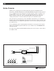
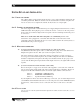
FIGURE 2: T17 TRANSMITTER CONTROLS Audio Indicator Light Level Control Flashes when audio signal is present. Screwdriver-adjust control used to set the microphone input level or the audio input level. Williams Sound Auditory Assistance Transmitter ON Indicator Light Mic Level Mic Input - 3.5 mm mini phone jack for use with Williams Sound condenser microphones. Supplies +DC power for condenser microphones. Glows when power is applied to the transmitter. There is no on/off switch.
SYSTEM CONTROLS AND FEATURES T17 TRANSMITTER FRONT PANEL MIC INPUT: 3.5 mm mini phone for use with Williams Sound condenser microphones. Supplies +DC power for condenser microphones. LEVEL CONTROL Screwdriver-adjust control used to set the microphone input level or the audio input level. ON INDICATOR LIGHT Glows when power is applied to the transmitter. There is no on/off switch. The T17 is designed to be left on continuously. AUDIO INDICATOR LIGHT Flashes when audio signal is present.
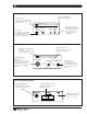
SYSTEM SET-UP AND INSTALLATION STEP 1: INSTALL THE ANTENNA The “rubber duckie” whip antenna fits into the hole on top of the transmitter and threads onto a mounting stud inside. Guide the antenna onto the stud and turn it clockwise to tighten. Do not use excessive force to tighten the antenna. It only needs to be “finger-tight.” STEP 2: CONNECT THE TRANSMITTER TO POWER The T17 is supplied with a wall transformer power supply. Plug the transformer into a 120 V, 60 Hz wall outlet.
TURNING OFF DC MICROPHONE POWER The T17 is designed to supply positive DC voltage to the plug tip of 2-wire, “barefoot” electret (power condenser) microphones. If you will be using the T17 with a non-Williams Sound, Lo-Z (dynamic) microphone, this DC power should be turned off. (See Figure 4.) If you use both the Microphone input and the Audio Input on the T17, the signals will be mixed together. Step 1: Unplug the power cord from the T17 and remove its antenna.
RECEIVER USE INSTRUCTIONS RECEIVER MODEL PPA R7 Receiver Model PPA R7 has a single, wheel-type volume control and an earphone output jack. BATTERY INSTALLATION Open the battery compartment using a coin in the slot in the bottom of the receiver. Press the battery into place, observing proper battery polarity. Incorrect insertion of the battery is difficult, and may cause both mechanical and electrical damage to the receiver not covered by the 5 year warranty.
Note: Some users may not be helped by this system. Severe hearing loss may require using the system with a telecoil coupler (i.e., Neckloop) and personal hearing aid. USING A RECEIVER WITH A HEARING AID Williams Sound PPA Receivers can be used with hearing aids using three different methods: NECKLOOP TELECOIL COUPLER Neckloops are cords which hang around the neck and couple magnetically with T-Coil equipped hearing aids.
BATTERY INFORMATION SINGLE USE BATTERIES In normal use, a heavy-duty 9 Volt battery such as the Eveready 216 will last about 10 hours. Alkaline batteries such as the Eveready 522 will provide about 32 hours of use. If the sound becomes weak or distorted, replace the battery. The indicator light may still be on, even with a battery that is weak. Do not leave dead batteries in the receivers. Battery corrosion is not covered by the Williams Sound five year warranty.
TROUBLE SHOOTING GUIDE TRANSMITTER “POWER” LIGHT NOT ON. þ Make sure the wall transformer is plugged into the transmitter. þ Make sure the electrical outlet is on. NO SOUND THROUGH RECEIVERS. þ If some of the receivers work, but others don't, check for bad batteries or earphones on the receivers that aren't working. þ Check to see that the receiver frequency matches the transmitter frequency. The frequency sticker is on the bottom of the transmitter and inside the back cover of the receiver.
2. Remove the screw from the center of the volume control and remove the knob. 3. Lift the clear plastic cover on the control and spray GC SPRA-KLEEN, LPS Contact Cleaner, or equivalent into the control. Replace the knob and rotate the control several times. 4. Replace the screw and close the case. BUZZING OR HUMMING NOISE IN SOUND SYSTEM. þ There is nothing wrong with the T17 Transmitter.
FREQUENCY CHANGE INSTRUCTIONS Normally, the PPA VPE’s factory-set channel (usually 72.9 MHz) requires no change. However, if another hearing assistance system or authorized radio service is operating on 72.9 MHz in your area, it may prove necessary to use an alternate channel In this event, the PPA VPE’s operating frequency can easily be changed to an alternate channel to avoid interference.
Step 4: Use a paper clip or small screwdriver (not a pencil point) to move the switches to correspond with the switch positions on the programming chart. (See Figure 6.) Select a new frequency at least two channels away from the one you are experiencing interference on. DO NOT TOUCH ANY OF THE OTHER ADJUSTMENTS! Step 5: Re-assemble the Transmitter and plug it in. Connect a tape player or radio to the transmitter to provide a tuning signal for the receivers.
RECEIVER FREQUENCY CHANGE INSTRUCTIONS Tuning for the R7, R30, R31, and R32 receivers is determined by a single tuning coil. In the R7-4 and R7-6, one coil is assigned to each switch position. See the following 6 figures and receiver types to locate the coils to be adjusted. A plastic tuning wrench (PLT 005) will be needed to adjust these receiver tuning coils.
Step 5: Locate the Tuning Coil. (See figure on previous page). Each tuning coil is a small, square, shiny metal can with a screwdriver slot in a tuning slug in the top center. The Tuning Slug is usually black or gray. Step 6: With the earphone or headphone supplied with the receiver plugged into the Ear Jack, turn the volume control to a comfortable level, and listen for the transmitted signal. Step 7: Gently put the tip of the tuning wrench into the slot in the tuning slug.
WARRANTY The Williams Sound T17 Transmitter and R7, R7-4, R7-6, and R16 Receivers are engineered and designed to provide you with many years of reliable service. Williams Sound warrants it against defects in materials and workmanship for FIVE (5) years EXCEPT FOR earphones, headphones, rechargeable batteries, chargers, cables, antennas, carry cases, and all other accessory products. Accessory products carry a 90 day warranty.
PERSONAL PA® VALUE PACK SYSTEM SPECIFICATIONS PERSONAL PA TRANSMITTER MODEL T17 Dimensions & Weight: 3.25" W x 6.875" L x 1.75" H (82.5 mm x 174.6 mm x 44.5 mm) 13 oz., 368.5 g Color: Black Power (U.S./Canada): 105-130 VAC, 50-60 Hz, .5 W Operating Frequencies: CH A (72.1 MHz), CH B (72.3 MHz), CH C (72.5 MHz), CH D (72.7 MHz), CH E (72.9 MHz), CH F (75.5 MHz) CH G (75.7MHz), CH H (75.9MHz), CH I (74.7 MHz), CH J (75.3 MHz), CH E (72.
Williams Sound Corp. 10321 West 70th St., Eden Prairie, MN 55344 U.S.A. 800-328-6190 / 952-943-2252 / FAX: 952-943-2174 www.williamssound.com © 2005, Williams Sound Corp.