® MANUAL AND USER GUIDE HEARING HELPER™ Tour Guide System Wireless, Portable FM Listening System Model TGS PRO 720 Transmitter Model PFM T32 or T31 Receiver Model PPA R35 MAN 122C
HEARING HELPER™ FM TOUR GUIDE SYSTEM, MODEL TGS PRO 720 INSTALLATION GUIDE & USER MANUAL Contents Page SYSTEM OVERVIEW 3 SYSTEM COMPONENTS 4 MICROPHONES 4 HEADPHONES & EARPHONES 5 SAFETY INFORMATION 6 RECYCLING INSTRUCTIONS 6 OPERATING INSTRUCTIONS PFM T32 TRANSMITTER PFM T31 TRANSMITTER PPA R35 RECEIVER 7 10 12 BATTERY INFORMATION BATTERY INSTALLATION RECHARGEABLE & NON-RECHARGEABLE BATTERIES USING OPTIONAL BATTERY CHARGERS 2 15 15 16 HINTS FOR USING THE SYSTEM 18 IN CASE OF DIFFICULT
SYSTEM OVERVIEW The HEARING HELPER™ Tour Guide System is a portable, high-performance, wireless system composed of the PFM T32 or T31 Transmitter and PPA R35 Receivers and designed for use in guided tour applications. The system allows one-way transmission of a tour guide’s voice to group members using an FM radio signal. Using the system helps group members overcome background noise and distance from the person speaking.
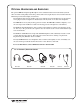
SYSTEM COMPONENTS Body Pack Transmitter (PFM T32 or T31) with (2) AA batteries (BAT 001) Noise-cancelling headband microphone (MIC 086) (10) Receivers (PPA R35) w/batteries (BAT 001) Instruction Manual (MAN 122) System carry case (CCS 030 S) THE PFM T32 OR T31 TRANSMITTER The PFM Transmitter is a battery-powered body-pack model used with a microphone to pick up the tour guide's voice. The transmitter produces an FM radio signal to broadcast the tour guide's voice to the receiver units.
OPTIONAL HEADPHONES AND EARPHONES The optional HED 021 Lightweight Headphone is the standard headset for the Tour Guide System. It offers excellent sound quality and wearing comfort. The foam earpads may be removed and washed in a mild detergent, rinsed thoroughly, and air dried. The headphone plugs into the “EAR” jack on top of the Receiver. The headphones are wired with a mono plug. If a stereo headphone is substituted, it will only work on one side of the headphone.
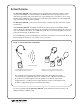
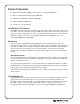
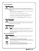
SAFETY INFORMATION HEARING SAFETY CAUTION! This product is designed to amplify sounds to a high volume level which could potentially cause hearing damage if used improperly. To protect your hearing and the hearing of others: 1. Make sure the volume is turned down before putting on the earphone or headphone. Then adjust the volume to a comfortable level. 2. Set the volume level at the minimum setting that you need to hear. 3.
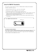
USING THE PFM T32 TRANSMITTER 1. Install two (2) AA batteries. If you’re using rechargeable batteries, they must be charged before using. 2. Plug the microphone cord into the “Mic” jack on top of the transmitter. FIGURE 3: T32 TOP VIEW 3. Place the transmitter in the belt clip case provided. 4. Slide the Power Switch on top of the transmitter to “On.” The Power ON LED indicator should illuminate Red. 5. The microphone should be placed as close to the speaker’s mouth as is practical.
CHANGING THE PFM T32 FREQUENCY FIG. 4: PFM T32 FREQUENCY CHANGE By default, the T32’s frequency is to set 75.7 MHz (Channel G). If you experience FM interference, or if you need to match a receiver’s frequency, it may be necessary to adjust the frequency on the T32. Instructions: 1. Open the battery compartment using a coin in the slot in the bottom of the transmitter. Remove the batteries. 2. Lift the battery compartment door up and pull to your left to expose the circuit board. 3.
ADVANCED FEATURES ON THE PFM T32 Gain Control Adjustment If necessary, the microphone gain control on the T32 can be increased or decreased to meet the demands of specific listening applications. FIG. 5: T32 ADVANCED FEATURES Instructions: 1. Open the battery compartment using a coin in the slot in the bottom of the transmitter. Remove the batteries. 2. Lift the battery compartment door up and pull to your left to expose the circuit board. 3. Refer to FIG 5 to locate the microphone gain control. 4.
USING THE PFM T31 TRANSMITTER Note: Before you begin, make sure you have AA Alkaline batteries installed in the transmitter. See Battery Information on page 15. 1. Plug the microphone into the “mic” jack on top of the transmitter. 2. Turn the power on: Place the FM switch to the “On” position. 3. Position the microphone as close to the speaker’s mouth as practical. 4. When you are ready to speak, turn the Mic Mute Switch to the “On” position.
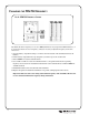
CHANGING THE PFM T31 FREQUENCY FIG. 7: PFM T31 FREQUENCY CHANGE Frequency Switches 1 2 3 4 5 6 7 8 Battery Compartment Switch Settings MHz 1 2 3 4 5 6 7 8 72.1 72.3 72.5 72.6 72.7 72.8 72.9 74.7 75.3 75.4 75.5 75.7 75.
USING THE PPA R35 RECEIVER Note: Rechargeable batteries are shipped in a discharged state and must be charged overnight before using. 1. Make sure there are two charged AA batteries in the Receiver. If batteries are not installed, see Battery Information on page 15. NOTE: The ON indicator will illuminate RED to indicate low battery. FIG. 8: PPA R35 RECEIVER TOP VIEW Earphone Jack On/Off Volume Switch "On" Indicator LED 2. Plug the earphone or headphone into the “Ear” jack on top of the Receiver. 3.
BELT CLIP INSTALLATION FOR PPA R35 TO INSTALL: Position the belt clip on the rear of the R-35 receiver as shown in Figure 9a. Turn the belt clip 180º left or right as shown in Figure 9b. The belt clip is now installed and ready for use. TO REMOVE: Turn the belt clip 180º so the edge points toward the top of the unit as shown in figure 9b. Gently pull the belt clip away from the unit to remove.
PPA R35 RECEIVER FREQUENCY CHANGE INSTRUCTIONS Selecting a frequency for the R35 receiver requires an adjustment to the internal tuning coil. See figure below to locate the coil to be adjusted. A plastic tuning wrench (PLT 005) will be needed to adjust this receiver’s tuning coil. FIGURE 10: LOCATING THE TUNING COIL IN THE RECEIVER TUNING COIL Ferrite Tuning "Slug" Alkaline NiMH Channel Tuning R-35 Most Williams Sound single channel Receivers are set at the factory to 72.9 MHz.
BATTERY INFORMATION INSTALLATION Open the battery compartment using a coin in the slot in the bottom of the receiver or transmitter. Press the batteries into place, observing proper battery polarity. Incorrect insertion of the battery is difficult, and if forced, may cause both mechanical and electrical damage to transmitters or receivers not covered by the five year warranty. Units will not work with the battery incorrectly installed.
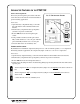
FIGURE 12: USING THE OPTIONAL CHG 200A BATTERY CHARGER TO CHARGE THE PFM T32 OR T31 TRANSMITTER Step 1: Plug the CHG 200’s power supply into the Power Input on the charger’s side and a standard AC wall outlet. Step 2: Route the power cord around the Cord Hook (see figure at right). This will minimize strain on the cord and jack and insure that the power cord is not detached during charging. Step 3: Make sure the transmitters to be charged are turned OFF.
USING THE OPTIONAL CHG 3512 BATTERY CHARGER TO CHARGE THE PPA R35 RECEIVER Before inserting the PPA R35 receivers into the charger, be sure that each receiver has NiMH batteries installed. Also, check to make sure the switch setting in the PPA R35 battery compartment indicates the “NiMH” setting. Step 1: Plug the TFP 035 power supply into the AC wall outlet. Plug the power connector into the rear of the CHG 3512 unit (See Figure 13a). Step 2: Insert the PPA R35 receivers into the charging slots.
HINTS FOR USING THE SYSTEM Normal operating distance between the transmitter and receiver is about 30 meters. The operating range will vary in different buildings and surroundings. In some locations, the signal may momentarily disappear. This is called a “drop-out” and is due to reflection and cancellation of the radio signal. Moving a few feet will restore the signal. Keep the transmitter and receiver units at least a meter apart.
IN CASE OF DIFFICULTY If your Tour Guide System is not working, check the following: 1. Read through the manual and user guide carefully to verify proper setup and installation of your system. 2. Make sure the batteries are fresh or completely charged and that the “plus” and “minus” terminals are installed correctly. 3. If the rechargeable batteries will only work for a short period of time (less than 1 hour) even after they are fully charged, they must be regenerated.
LIMITED WARRANTY Williams Sound products are engineered, designed, and manufactured under carefully controlled conditions to provide you with many years of reliable service. Williams Sound warrants the HEARING HELPER™ Tour Guide System against defects in materials and workmanship for FIVE (5) years. During the first five years from the purchase date, we will promptly repair or replace the HEARING HELPER™ Tour Guide System.
SYSTEM SPECIFICATIONS FM TRANSMITTER, MODEL PFM T32 Dimensions: Weight: Color: Battery Type: Operating Freq’s: Stability: Modulation: RF Output: Freq Response: Signal-to-Noise Ratio: Microphone Gain Control: Transmit Antenna: Microphone: Controls: Mic Connector: Compatible Receivers: Approvals: Warranty: Note: 3-5/8" L x 2-3/8" W x 7/8" H (92.1 mm x 60.3 mm x 22.2 mm) 4.4 oz (125 g) with battery Royal blue, shatter-resistant polypropylene Two (2) AA 1.
RECEIVER, MODEL PPA R35 Dimensions: Weight: Color: Battery Type: Current Consumption: Operating Freq.: Intermediate Freq.: FM Deviation: De-Emphasis: LED Indicator AFC Range: Sensitivity: Input Overload: Frequency Response: Signal-to-Noise Ratio: Receive Antenna: Audio Output: Output Connector: Earphone: Notes: Approvals: Warranty: 4.1" L x 2.85" W x 1.2" H (104.1 mm x 72.4 mm x 30.4 mm) 4.5 oz (127 g) Gray Two (2) AA non-rechargeable alkaline batteries (BAT 001), approx.
® 10321 West 70th St., Eden Prairie, MN 55344 U.S.A. 800.843.3544 | 952.943.2252 | FAX: 952.943.2174 www.williamssound.com © 2006, Williams Sound Corp.