
Installation guide


8
TX10
Coverage area
with Single Emitter
Coverage area
with Second Emitter
Added to Same
Emission Point
(50% increase)
TX8
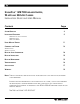
Multiple Emitters Installed to Maximize Coverage
FIG. 5a: Overlapping Illumination Patterms to Cover Larger Listening Areas
FIG. 5b: Using Two Emitters at Same Emission Point to Increase Coverage Area
Fig. 5a above is a typical example of how multiple emitters are used to cover larger listening areas.
Generally, it is desirable for the illumination patterns to overlap. Note: The coverage area will vary
depending on the infrared receiver being used; refer to Figures 2 and 4 to determine how many emitters
are required to achieve full coverage of a listening area.
When two emitters are used at the same emmission point in single channel mode, the overall coverage area
increases 50%. When using an RX3 receiver, as a result, the coverage area will increase to 15,000 ft
2
(1,393
m
2
); the RX7/8 will increase to 9,000 ft
2
(836 m
2
); and the RX4 will increase to 6,000 ft
2
(557 m
2
).
TX10 TX8
TX8 TX8