Installation Guide & User Manual SoundPlus ® WIR TX10 Infrared Transmitter, Selectable 95 kHz or 250 kHz Carrier Large Area Infrared Listening System Modulator-Transmitter Model WIR TX10 MAN 085H ® Williams Sound Helping People Hear
SOUNDPLUS ® WIR TX10 INFRARED TRANSMITTER, SELECTABLE 95 KHZ OR 250 KHZ CARRIER INSTALLATION GUIDE AND USER MANUAL Contents Page SYSTEM OVERVIEW 4 INSTALLATION PROCEDURE 6 TX10 TRANSMITTER COVERAGE PATTERNS TX10 TRANSMITTER SETUP TX10 POWER WIRING AUDIO SOURCE CONNECTION TESTING THE SYSTEM CONTROLS AND FEATURES 14 TX10 REAR PANEL TX10 BOTTOM PANEL RECEIVER INSTRUCTIONS 17 RECEIVER MANAGEMENT 17 USING MULTIPLE EMITTERS 16 TROUBLESHOOTING 18 WARRANTY 20 SPECIFICATIONS 21 NOTES: TAKING A
SYSTEM OVERVIEW The Williams Sound WIR TX10 Infrared Transmitter uses invisible infrared (IR) light waves to broadcast speech or music to wireless infrared receivers. The TX10 accepts a balanced or unbalanced line level audio input and emits an invisible infrared 95 kHz or 250 kHz frequency throughout the listening area. Infrared receivers detect the transmission and convert the light signals back into audio signals.
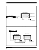
FIGURE 1A: TYPICAL SYSTEM CONFIGURATIONS TX10 Transmitter Baseband LED (Visible From Below) Audio Source Power On LED (Visible From Below) Amplifier 3 2 1 Power 4 5 6 7 8 9 3 2 1 10 0 Level 4 5 6 7 8 9 3 2 1 10 0 Level 4 5 6 7 8 9 3 2 1 10 0 Level 4 5 6 Line Level Output Phones 7 8 9 10 0 Level Audio Audio Limit Limit Compress Compress Audio Input Audio LED (Visible From Below) Power Supply 120 VAC (US): TFP 010 230 VAC (CE): TFP 027 FIGURE 1B: ADDING A TX8 EMITTER FOR GREATER
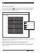
TX10 TRANSMITTER COVERAGE PATTERNS The coverage area for the TX10 will vary depending on the receiver being used. Figures 2 and 4 demonstrate the receiver coverage area when operating a single TX10 transmitter in single channel mode. Generally, an RX3 receiver will operate up to 10,000 ft2 (930 m2); a RX7/8 receiver will operate up to 6,000 ft2 (560 m2); and a RX4 receiver will operate up to 4,000 ft2 (370 m2).
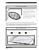
FIG 3a: 3-Dimension Foot Pattern The TX10 floods the listening audience with a cone shape light pattern as shown here. The path of the cone shape light leaves a pattern on the ground, or "foot print," and indicates where the strongest receiver reception will occur. The actual coverage area will vary depending on the signal strength of the receiver being used. Refer to Figures 2 and 4 to determine how many emitters are required for 100% coverage of the listening area.
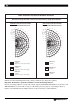
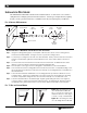
FIG 4: Horizontal and Vertical Radiation Polar Plots Receiver Coverage Area with a TX8 or TX10 Transmitter in Single Channel Mode HORIZONTAL RADIATION POLAR PATTERNS DISTANCE FROM EMITTER TO RECEIVER 120 30 – 90 – 70 – 60 – 50 100 24 80 18 60 12 40 6 20 – 40 – 30 42 140 36 120 30 – 80 – 70 – 60 – 50 100 24 80 18 60 12 40 6 20 – 20 – 10 FEET 36 – 80 METERS 140 FEET METERS – 90 42 VERTICAL RADIATION POLAR PATTERNS DISTANCE FROM EMITTER TO RECEIVER – 40 – 30 – 20 – 10 0
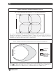
Multiple Transmitters Installed to Maximize Coverage FIG. 5a: Overlapping Illumination Patterms to Cover Larger Listening Areas TX10 TX8 TX8 TX8 Fig. 5a above is a typical example of how multiple transmitters are used to cover larger listening areas. Generally, it is desirable for the illumination patterns to overlap.
INSTALLATION PROCEDURE The TX10 Infrared Transmitter should not be installed outdoors, or where there is a lot of direct sunlight indoors. Sunlight generates infrared interference. Certain types of high-efficiency lighting fixtures can also generate interference at 95 kHz because they use high frequency modulation. FIG.
INSTALLATION STEP 2: TX10 TRANSMITTER POWER WIRING POWER SUPPLY FOR THE TX10 The TX10 must be supplied power from a Limited Power Source as defined by EN 60950:1992; Clause 2.11. Units operated from 120 VAC must use Williams Sound part number TFP 010. Units operating from 230 VAC must use Williams Sound power supply part number TFP 027/UK. WARNING: POWERLINE VOLTAGE MUST NOT FALL BELOW 94V, OR SYSTEM PERFORMANCE WILL BE GREATLY REDUCED! FOR U.S.
INSTALLATION STEP 3: AUDIO SOURCE CONNECTION The WIR TX10 accepts audio signals from balanced or unbalanced line level outputs, transmitting audio with excellent fidelity. Therefore, be sure to connect its input to the highest quality audio source your system can offer. Step 1: Determine the length of cable needed to reach from the audio source to the TX10 Transmitter. You will need to cut it to length. Make sure you leave some slack at each end.
INSTALLATION STEP 4: TESTING THE SYSTEM Step 1: After the power cable and audio source are connected, the Power LED indicator on the right side of the the bottom panel should light. Step 2: Make sure the sound system is on and your audio source is active. Turn the Audio Input Adjust if necessary. (See Figure 9.) Step 3: Look at the TX10's bottom panel.
CONTROLS AND FEATURES WIR TX10 REAR PANEL POWER IN 21 VAC to 26 VAC only, 50 or 60 Hz (120 VAC [US]: TFP 010 Power Supply / 230 VAC [CE]: TFP 027 Power Supply). Consumption is 35 VA. AUDIO INPUT The WIR TX10's input circuit is constructed with a differential amplifier, providing better performance than that available using a transformer. It is fully protected from RFI/EMI. Both balanced and unbalanced line level signals can be accommodated.
“looping through” the connected device or by means of a suitable distribution amplifier. The output impedance is 50 Ω. Frequency accuracy is better than ± .010%. Deviation is ± 50 kHz, maximum. WIR TX10 BOTTOM PANEL POWER LED Indicates actual operation of the transmitter. Does not indicate status of power supply. FREQUENCY SWITCH This slide switch selects between carrier frequencies of 95 kHz and 250 kHz. Accessed through holes in chassis bottom. AUDIO INPUT ADJUST Controls level of audio signal.
USING MULTIPLE EMITTERS Listening areas of more than 10,000 square feet (930 square meters) will require a TX10 and at least one TX8 Emitter for complete coverage. Place one TX10 transmitter on the left side of the front wall and one TX8 emitter on the right hand side. For extremely large venue, additional TX8s should be located to maximize coverage throughout the listening area. Figures 5a and 5b illustrate infrared light patterns and recommended emitter locations.
IR RECEIVER MODELS WIR RX3, WIR RX7, WIR RX8 Make sure the “eye” on the front of the receiver is not covered up when in use. The receiver is intended to be worn on the front of the body, hanging from the lanyard attached to the receiver. The receiver will not work if it is placed in a pocket or purse. A variety of earphones, headphones, or neckloop telecoil couplers can be used with RX3, RX7 and RX8 Receivers.
Regular users purchase their own earphone or headphone and bring them to use with receivers at the facility. Some facilities use the drop-in style CHG 200 or CHG 1269 Multi-charger for both storing and charging receivers TROUBLESHOOTING NO INDICATOR LIGHTS ARE ON (FIG 9). Make sure the wall transformer is plugged into the transmitter and the power switch or any remote power switch is on. Make sure the electrical outlet is on. Make sure the 24 VAC power supply is working.
13B FIGURE 13: BNC CONNECTOR ASSEMBLY Washer 7.92 mm (± .25) .312 in. (± .01) Grooved Side Nut Gasket (note groove) Nut Cable Jacket Washer Plug Assembly Gasket 13C Clamp Contact Clamp positioned against Cable Jacket ASSEMBLY PROCEDURE 13D The BNC Connector consists of a plug assembly, a contact, a clamp, a gasket, a washer, and a nut. 1. Slide nut, washer and gasket over cable end; then strip outer cable jacket using the recommended strip-length dimension in figure 13b.
Warranty The Williams Sound WIR TX10 Infrared Transmitter is engineered and designed to provide you with many years of reliable service. Williams Sound warrants against defects in materials and workmanship for FIVE (5) years EXCEPT FOR earphones, headphones, rechargeable batteries, charger, cables, antennas, carry cases, and all other accessory products. Accessory products carry a 90 day warranty.
SoundPlus® WIR TX10 Infrared Transmitter Specifications INFRARED TRANSMITTER, MODEL TX10 Dimensions, Weight: 11.25" W x 6.25" H x 2.125" D (28.6 cm x 15.9 cm x 5.4 cm) 1.9 lbs. (0.9 kg) Color: Black anodize with white legends, red acrylic window Wall Mount: BKT 024 mounting bracket included for wall and ceiling mounting. Tripod Mount: Optional SS-6 Tripod Stand Kit available Operating Req.
INFRARED RECEIVERS, MODELS WIR RX7 & WIR RX8 (OPTIONAL) Size and Weight: Color and Material: Battery Type: Battery Life: Modulation Frequency: Signal to Noise Ratio: Controls: Audio Output: Acoustic Output: 3-5/8" L x 2-3/8" W x 7/8" H (9.2 cm x 6 cm x 2.4 cm) 4.48 oz. (127 g) Grey, shatter-proof polypropylene 1.5V (AA) x 2, Alkaline (BAT 001) or Rechargeable AA NiMH (BAT 026) 30 hours with BAT 001, 15 hours/charge with BAT 026, 25 mA, nom.
RECYCLING INSTRUCTIONS BATTERY SAFETY AND DISPOSAL Help Williams Sound protect the environment! Please take the time to dispose of your equipment properly. Product Recycling for Customers in the European Union: Please do NOT dispose of your Williams Sound equipment in the household trash. Please take the equipment to a electronics recycling center; OR return the product to the factory for proper disposal.
Williams Sound Corp. 10321 West 70th St., Eden Prairie, MN 55344-3459 U.S.A. 800-328-6190 / 952-943-2252 / FAX: 952-943-2174 24 www.williamssound.com © 2005, Williams Sound Corp.