
Instructions / Assembly


Blower Accessory 2102
Accessories– 27
Mounting the Blower
Note: All electrical work must conform to your local codes and ordinances or in their absence, with National Electrical Code,
ANSI/NFPA 70. If you are not familiar with wiring codes in general, have a competent electrician do this job. In CANADA: CANADIAN
ELECTRICAL CODE C22.1.
WARNING: Danger of property damage, bodily injury or death. Turn off electrical power supply at
disconnect switch, fuse box or service panel before removing or working on fan.
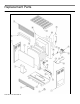
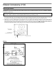
1. Place the motor and blower on the heater floor, securing with four (4) screws. Attach three (3) screws to the inlet duct and one (1)
screw to the heater floor, using the existing screw holes. Align the opening in the base of the motor and blower with the opening in
the heater floor. The opening on the side of the motor and blower should align with the opening on the heater inlet duct.
2. Attach the “HI” and “LO” speed switch to the upper left corner on the back of the heater and replace the corner bracket with the
speed switch plate using the existing mounting holes. The correct position for the fan switch is shown below. The top of the fan
switch should be level with the notch directly across the switch on the blower mounting plate. Make sure speed switch wires are
secured with clamp (provided in the kit) away from the combustion chamber before operating the heater.
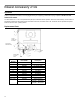
Wiring
Attach clamp to secure wires
Air Inlet Duct
Correct position
of fan switch
Run switch wire
through attached clamp