
Full Product Manual

Introduction
Introduction – 5
Please read our instructions before you install and use your furnace. This will help you obtain the full value from this furnace. It will also
help you avoid any needless service costs if the problem is found within this instruction manual.
Always consult your local heating or plumbing inspector, building department or electric utility company regarding regulations, codes or
ordinances which apply to the installation of a Direct-Vent Wall Furnace.
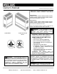
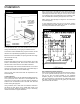
Basic Description
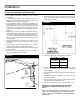
Your direct-vent wall furnace is shipped ready to install against an
exterior wall up to 9 inches thick. For walls greater than 9 inches,
and up to 24 inches thick, use an optional Vent Extension Kit.
The furnace may burn either Natural or L.P. Gas, depending on
the model you have purchased.
No electric power is required unless furnace is equipped with an
optional blower accessory.
Always consult your local heating or plumbing inspector, building
department or gas utility company regarding regulations, codes or
ordinances which apply to the installation of a direct-vent furnace.
The sealed combustion system draws combustion air directly from
outdoors into the combustion chamber and combustion gases are
discharged directly outdoors through tubes on the rear of the
furnace.
The furnace cabinet is also constructed of heavy-gauge steel and
has a powder paint finish.
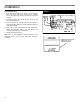
The furnace controls are located behind an access door on the
lower front of the furnace. All models are equipped with American
Gas Association and Canadian Gas Association (AGA/CGA)
listed gas valves and pilots.
Tools Needed
Hand drill or properly grounded electric drill
6 ft. folding rule or tape measure
Screwdrivers (Phillips Head)
Pliers (wire cutting)
Stud locator or small finishing nails.
Tin snips
8 and 12 inch adjustable wrenches
Keyhole or sabre saw
(2) 10 inch or 12 inch pipe wrenches
Gloves and safety glasses
Materials
Pipe joint compound resistant to L.P. gases.
Caulking compound-silicone rubber with a temperature rating of
500
°F.
DO NOT use caulking advertised as paintable or for bathtub use
as most contain fillers and will not withstand high temperatures.
Pipe and fittings to make connections to the furnace.
Electrical wiring supplied as needed for optional blower.
Minimum wire size is #14 gauge copper.
Helpful Installation Information
The following booklets will help you in making the installation:
ANSI/NFPA 70, or current edition "National Electrical Code". In Canada: CSA C22.1 Canadian Electrical Code.
American National Standard Z223.1 or current edition "National Fuel Gas Code".
Obtained from: American National Standards Institute, Inc., 1430 Broadway, New York, N Y 10018. In Canada: CAN/CGA B149.
Optional Accessories
Vent Extensions: For walls greater than 9 inches thick and up to 24 inches thick, use one of the following Vent Extension Kits:
Kit Number Wall Thickness Models
9301 9 inches to 15 inches 22038 and 30038 Series
9302 15 inches to 24 inches 22038 Series
9303 15 inches to 24 inches 14038 and 30038 Series
9304 9 inches to 15 inches 14038 Series
Blower Accessories 2302, 2303 – To increase circulation of warmed air within the heated space, you may use Blower Accessory Kit
2302, for model series 22038 or Kit 2303 for model series 14038. Both are equipped with a two- speed fan and an automatic fan switch.
Thin Wall Collar Kit 9307 – For walls less than 4-1/2 inches thick, a Thin Wall Collar Kit may be used to increase wall thickness.
Vent-Cap Guard 9308 – This mounts to the outside of the exterior wall over the vent cap, to protect pedestrian traffic from heat.
Vent Shield Deflector 4318 – Insulated, galvanized sheet for all direct-vent models. Thermostat P322016
Gas Conversion Kits – Used to convert your furnace from Natural Gas to L.P. Gas and from L.P. Gas to Natural Gas. See page 12.