
Instructions / Assembly


Installation Instructions
Blower Accessor
y
– Model No. 2302
The automatic fan switch “E” turns on the blower after the furnace has been operating a few minutes and turns off the
blower after the furnace shuts off. The blower will not operate unless the fan switch (pull chain) is pulled to the “ON
position, either “HIGH” or “Low”. To check the fan switch (pull chain) position, turn the automatic fan switch dial “E” to
70, then pull the chain on the fan switch to obtain the high, low or off position. Set the automatic fan switch dial to 110
and readjust it higher or lower as necessary to obtain blower operation with 4 to 5 minutes after the furnace burner is in
operation. This accessory can be operated by using the factory equipped three-prong (grounding) plug and cord or may
be field wired. When using the plug and cord, for your protection against shock hazard, it must be plugged directly into a
properly ground three-prong receptacle. DO NOT CUT OR REMOVE THE PRONG. All electrical work must conform to
your local codes and ordinances or in their absence, with National Electrical Code ANSI/NFPA 70. In Canada,
Canadian Electrical Code C22.1. If you are not familiar with wiring codes in general, have a competent electrician do
this job. Refer to your furnace owner’s manual for additional information. Be sure this accessory is of the type and
design required for use with your furnace.
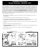
1. Mounting Blower to the Furnace: Remove the knock-out plates “A” and “B” from right side of the furnace. As
shown in Figure A.
2. Remove the junction box cover and place blower and junction box in position as shown.
3. Attach the blower and junction box to the inner casing using the pre-punched holes with screws “C” and “D”
provided with this kit. See illustration below for proper mounting hole to use with your model.
4. After blower and junction box are installed, rotate bushing “H” needed to prevent motor wire from binding against
blower case.
5. Plug in factory supplied three-prong (grounding) plug and cord.
1. Field Wiring Installation Instructions: Remove junction box cover and disconnect factory installed three prong
(grounding) plug and cord.
2. Install 115V line in accordance with local codes, connecting as shown on the wiring diagram below.
3. Replace junction box cover.
BLOWER MODEL 2302
FIELD WIRING
FIGURE A ATTACH BLOWER USING THESE (2) HOLES