INSTALLATION & OPERATING INSTRUCTION MANUAL owners manual MODEL NOS. 2509612 2509622 GAS-FIRED TOP VENT GRAVITY WALL FURNACE READ THIS OWNERS MANUAL CAREFULLY BEFORE YOU INSTALL YOUR NEW IMPROVED EFFICIENCY WILLIAMS WALL FURNACE WARNING: If the information in this| manual is not followed exactly, a fire or explosion may result causing property damage, personal injury or loss of life. -- -!ii_I MODEL NO_:!i_ 2509611 2509621 3509611 3509621 5009611 5009621 FOR USE WITH LIQUEFIED PETROLEUM (L.P.
Contents Williams Installation Policy ...................... Introduction .................................. Basic Description .............................. Helpful Installation Information ................... Safety Rules ................................. Unpack Your Furnace .......................... Basic Tools Needed ............................ Basic Materials ............................... Optional Accessories ........................... Installing Your Wall Furnace .....................
A Word From The Manufacturer Dear Customer, To set up our furnace assembly procedures, several hundred quafity assurance, safety audit and design performance tests have been conducted according to the standards provided by the American National Standards Institute, the Department of Energy and our certification agency -- the American Gas Association Laboratories. This was done to assure you of receiving the best value and most reliable appliance of its type available today.
Safety Rules WARNING umn. The maximum inlet gas supply pressure is 13" water column. READ THESE RULES AND THE INSTRUCTIONS CAREFULLY. FAILURE TO FOLLOW THESE RULES AND INSTRUCTIONS COULD CAUSE A MALFUNCTION OF THE FURNACE. THIS COULD RESULT IN DEATH, SERIOUS BODILY INJURY, AND/OR PROPERTY DAMAGE. 7. ANY SAFETY SCREEN, GUARD OR PARTS REMOVED FOR SERVICING AN APPLIANCE MUST BE REPLACED PRIOR TO OPERATING THE APPLIANCE TO AVOID PROPERTY DAMAGE, BODILY INJURY OR DEATH.
Unpack Your Furnace The shipping carton contains the furnace and the items needed to install it: 4. Stand Furnace upright. 5. Properly dispose of shipping material. The furnace is shipped assembled. The cabinet must be removed for the furnace installation. NOTE Check the burner rating plate, located in burner compartment, to make sure your furnace is equipped to operate on the type of gas available (either Natural or L.P. Gas). DO NOT convert unit from Natural Gas to L.R Gas or from L.
Installing Your Wall Furnace The following steps are all needed for proper installation and safe operation of your furnace. If you have any doubts as to any requirements, check with local authorities. Obtain professional help where needed. Locating All of CHECKS AND ADJUSTMENTS in the Start-Up Procedure on page 17 are vital to the proper and safe operation of the furnace. Be sure they are done.
Combustion & Ventilation Air WARNING WARNING DANGER OF ILLNESS BODILY INJURY OR DEATH THE FURNACE AND ANY OTHER FUEL BURNING APPLIANCE MUST BE PROVIDED WITH ENOUGH FRESH AIR FOR PROPER COMBUSTION AND VENTILATION OF FLUE GASES. MOST HOMES WILL REQUIRE THAT OUTSIDE AIR BE SUPPLIED INTO THE FURNACE AREA.
Combustion To determine if infiltration following checks: & Ventilation air is adequate, perform the Air (Con't) Provide an opening(s) having a total free area of 1 sq. inch per 4000 Btuh of the total of all appliances. The required area is shown in Fig. 7, page 9. 1. Close all doors and windows. 11you have a fireplace, start a fire and wait until flames are burning vigorously, (or flue damper can be closed), FRESH AIR DUCT 2.
Combustion & Ventilation A. All Air From Inside Building: If the confined space adjoins an unconfined space as defined in EXAMPLE 1, provide two permanent openings, one within 12 inches of the top and one within 12 inches of the bottom of the room connecting directly to unconfined space. Each opening must have a free area of at least 100 square inches or 1 square inch per 1000 Btuh combined input of appliances in one room if combined input exceeds 100,000 Btuh.
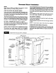
Recessed Mount NOTE: Model Series 25096 and 35096. The maximum recess depth, from rear of furnace forward is 41/=''. Installation rear outlet plasterground at the same time you install the header plate. For existing construction, make necessary cutout and install the plasterground just before you install the furnace. See instructions packed with kit and Fig. 8. FIND THE STUDS AND CEILING JOISTS Use a stud Iocator or small finishing nails.
Recessed Mount Installation (Con't) CEILING PLATE SPACERS RECESSED MOUNT CLOSE OFF STUD SPACE 14 3/8 PLA'flE I_- EXISllNG STUD I]I CEILING PLATE SPACERS NAILED IN BE'nNEEN CEILING PLATES OR ACROSS FACE IF ACCESSIBLE NEW STUD III _S_NG S'PJD -_ _A_ I [ II BLOCKS •.-- 14--3/8" [ FLOOR III HI III CUT PLATE OPENING (RECESSED VENTING) OPTIONAL ELECTRICAL OUTLET Cut away the ceiling plate between the studs where the furnace is to be installed. Work from the top in the attic.
Surface Mount Installation Vent Installation The use of optional Free Standing Kit No. 4901 allows furnace to be mounted on the surface of a wall. See detailed instructions packed with kit. Vent Installation The vent installation must comply with all local codes and ordinances. If in doubt, consult your local codes or inspector. The furnace vent must be directed to the outdoors so that harmful combustion gasses will not collect inside the building.
Mount POSITION f The Furnace URING FURNACE LEGS NEAR FLOOR PLATE FURNACE BOTTOM OF FURNACE B/W VENT NAIL FURNACE LEG TO STUD OR (SEE DETAIL BELOW) LEG _ FLOiR PLATE MODELS ANGLE 2509612 2509622 3509612 3509622 AND _FLOOR PLATE 2509611 2509621 IMPORTANT AVOID NAILING THE LEGS SO TIGHTLY THAT IT DISTURBS THE INNER FURNACE CASINGS. DO NOT TRY TO FORCE THE FURNACE INTO A SMALLER-THAN-SPECIFIED RECESS. 3509611 3509621 Clear the recess of a!l debris, remove any wood plastergrounds.
Gas Supply and Piping Gas control valve, within the furnace, is shipped with a sealed cover gas inlet tapping. Do not remove seal until ready to connect piping. WARNING DANGER OF PROPERTY DAMAGE, BODILY INJURY OR DEATH. MAKE SURE THE FURNACE IS EQUIPPED TO OPERATE ON THE TYPE OF GAS AVAILABLE. MODELS DESIGNATED AS NATURAL GAS ARE TO BE USED WITH NATURAL GAS ONLY. FURNACE DESIGNATED FOR USE WITH LIQUEFIED PETROLEUM (L.P.) GAS HAVE ORIFICES SIZED FOR COMMERCIALLY PURE PROPANE GAS.
Gas Supply CHECKING and Piping (Con't) THE GAS PIPING GAS PIPE SIZES Test all piping for leaks. When checking gas piping to the furnace with gas pressure at less than 1/2 PSI, shut off manual gas valve for the furnace, if gas piping is to be checked with the pressure at or above 1/2PSI, the furnace and manual shut off valve must be disconnected during testing. (SEE WARNING BELOW.) Apply soapsuds (or a liquid detergent) to each joint. Bubbles forming indicates a leak.
Thermostat MOUNTING Installation (Con't) THE THERMOSTAT ROUTE THERMOSTAT CABLE 1. To remove thermostat cover, squeeze both sides and lift. Carefully remove and discard the packing tab protecting the switch contacts. 2. Connect thermostat wires to the terminal screws on the back of thermostat base. 3. Push any excess wire back through hole in wall and plug hole with insulation to prevent drafts from affecting thermostat operation. 4.
Cabinet B*'WVENT_ installation PANEL ATTACHING SCREW IG B/W ! SCREW EA SIDE MODELS MODELS 2509611 2509612 2509621 2509622 5009611 5009612 5009621 5009622 AND 3509611 3509612 3509621 3509622 BOTTOM PANEL MENT (2} SCREWS EACH SIDE CASING/ LEGS PANEL DOOR (CONTROL) (CONTROL) FLOOR LEGS PLAlr E FLOOR Place panel top over channel on header plate, as shown in Fig. 21. Press panel tight against wall, and secure it to header with screw provided in final assembly package.
Start.Up Procedure (Con't) CHECK THE GAS INPUT (NATURAL GAS ONLY) -WARNING NATURAL GAS HEATING VALUE (BTU PER CUBIC FOOT) CAN VARY SIGNIFICANTLY, THEREFORE, IT IS THE INSTALLERS' RESPONSIBILITY TO SEE THAT BTU INPUT TO THE FURNACE IS ADJUSTED PROPERLY. FAILURE TO DO SO COULD CAUSE HEAT EXCHANGER FAILURE, ASPHYXIATION, FIRE OR EXPLOSION, RESULTING IN DAMAGE, BODILY INJURY OR DEATH. REFER TO THE NATIONAL FUEL GAS CODE (NFPA-54) TO BE SURE THE FURNACE IS BURNING FUEL AT THE PROPER RATE.
FOR YOUR SAFETY, WILLIAMS READ GAS CONTROL BEFORE LIGHTING VALVE P322051 & P322052 I I WARNING: If youcausing do not property follow these Instructions a firs may result damage, personal exactly, injury or lossorofexplosion life. A. This appliance has a pilot which must be Ilghfed by hand. When lighting the pilot, follow these instructions exactly. B. BEFORE LIGHTING smell around the appliance area for gas.
FOR YOUR SAFETY, WILLIAMS READ BEFORE GAS CONTROL LIGHTING VALVE P295100A & P295101A I WARNING: If youcausing do not property follow these instructions a fire may result damage, personal exactly, injury or lossorofexplosion life. A. This appliance has a pilot which must be lighted by hand. When lighting the pilot, follow these Instructions exactly. B. BEFORE LIGHTING smell around the appliance area for gas.
Operating MODELS 2509621; 2509622; SAFETY, OPERATING 3509621; 3509622; Your Furnace 5009621 5009622 AND SHUTDOWN All models listed above are equipped with a Williams gas control valve part number P172100A; P172200A (see page 22) or part number P295000A; P295001A (see page 23). The furnace operates like this: 1. Thermostat turns on the main burner. 2. Heat builds up in the furnace and starts the fan (if equipped). The heated air comes out the front panel louvers. 3.
FOR YOUR SAFETY, WILLIAMS READ BEFORE GAS CONTROL LIGHTING VALVE P172100A & P172200A WARNING: If you do not follow these instructions exactly, a fire or explosion may result causing property damage, personal Injury or loss of life. A. This appliance has a pilot which must be lighted by hand. When lighting the pilot, follow these Instructions exactly. B. BEFORE LIGHTING smell around the appliance area for gas.
FOR YOUR SAFETY, WILLIAMS READ BEFORE GAS CONTROL LIGHTING VALVE P295000A & P295001A I WARNING: If youcausing do not property follow these instructions a fire may result damage, personal exactly, injury or lossorofexplosion life. A. This appliance has a pilot which must be lighted by hand. When lighting the pilot, follow these Instructions exactly. S. BEFORE LIGHTING smell around the appliance area for gas.
How To Care For Your Furnace BURNER FLAME WARNING DANGER OF BODILY INJURY OR DEATH Start the furnace and let it operate about 10 minutes then look at the burner flame. Flames should be soft and blue, see Fig. 23. If flames appear abnormal, contact the gas company or a qualified service technician immediately. TURN OFF ELECTRIC POWER SUPPLY AT DISCONNECT SWITCH, FUSE BOX OR SERVICE PANEL BEFORE REMOVING ANY DOORS OR ACCESS OR SERVICE PANELS FROM UNIT. NOTE CABINET FINISH Clean cabinet with damp rag.
How To Care For Your Furnace WARNING I (ton't) in the burRer area will occur each heating season. It is necessary to clean this area regularly. Use a vacuum cleaner with a narrow attachment to reach small areas. Be careful in and around the pilot. A change in its adjustment could be made if struck during cleaning. MAKE SURE GAS SUPPLY IS OFF BEFORE DANGER PANELS OF BODILY INJURY OR DEATH REMOVING OR DOORS, ETC. BURNER CLEANING FURNACE CONTROLS Check burner.
TROUBLE SHOOTING WILLIAMS SYMPTOM 1. Pilot will not stay lit after carefully following lighting instructions. GAS-FIRED TOP VENT GRAVITY POSSIBLE CAUSES WALL FURNACE CORRECTIVE ACTION A. Thermocouple or generator producing insufficient millivoltage. Check pilot flame - must impinge on thermocouple or generator. Be sure thermocouple or generator is fully inserted in bracket. B. Loose or dirty thermocouple or generator connections at gas valve.
TROUBLE SHOOTING WILLIAMS SYMPTOM GAS-FIRED TOP VENT POSSIBLE CAUSES GRAVITY WALL FURNACE CORRECTIVE ACTION 3. Furnace operates but turns "Off" before room temperature is attained. (continued) C. Thermostat location. (Wall thermostat model.) Check thermostat location - should not be in the path of warm air discharge from furnace, near a lamp, or above a TM. or stereo set. D. Defective thermostat. (Wall thermostat model.) Check thermostat calibration or replace. 4.
WILLIAMS GAS-FIRED TOP VENT GRAVITY WALL FURNACE REPLACEMENT PARTS 2509611; 2509612; 3509611; 3509612; REF. NO. PART LIST FOR 2509621; 3509621; MODELS 2509622 3509622 - DESCRIPTION NO. 1 4915 FACE PANEL 2 9C155 FRONT HEAT SHIELD 3 9D52 COMBUSTION CHAMBER ASSY.- 3 9D54 COMBUSTION CHAMBER ASSY. 4 9B199 DEFLECTOR 5 9C153 INNER SHIELD TOP 6 9C166 DRAFTHOOD ASSEMBLY- 2509611; 2509612; 2509621; 2509622 6 9C165 DRAFTHOOD ASSEMBLY- 3509611; 3509612; 3509621; .
WILLIAMS GAS-FIRED TOP VENT GRAVITY WALL FURNACE REPLACEMENT PARTS FOR 2509611; 2509612; 2509621; 3509611; 3509612; 3509621; MODELS 2509622 3509622 I I USE ONLY MANUFACTURER'S AUTHORIZED PARTS =,,_ ip,lo.
WILLIAMS GAS-FIRED TOP VENT GRAVITY WALL FURNACE CONTROL ASSEMBLY REPLACEMENT PARTS LIST FOR MODELS 2509611; 2509612; 2509621; 2509622 3509611; 3509612; 3509621; 3509622 _;_ REF. NO. PART NO.
WILLIAMS GAS-FIRED TOP VENT GRAVITY REPLACEMENT 2509611; 2509612: 2509621; 2509822; 3509811; FOR REPLACEMENT PARTS LISTING NAT. GAS CONTROL ASSEMBLY L.P.
WILLIAMS GAS - FIRED TOP VENT GRAVITY WALL FURNACE REPLACEMENT PARTS LIST FOR MODELS 5009611; 5009612; 5009621 ; 5009622 REF. PART NO. NO. DESCRIPTION 1 4.915 FACE PANEL (2 REQUIRED) 2 9C155 FRONT HEAT SHIELD (2 REQUIRED) 3 9A277 CARRYOVER SHELL 4- 9D65 COMBUSTION 4A 9073 COMBUSTION CHAMBER ASSEMBLY (REAR) 5 9C171 OUTER CASING ASSEMBLY 6 95199 DEFLECTOR 7 5901 HEADER 8 P321826 UMIT SWITCH CHAMBER ASSE]_BLY (FRONT) (REF.
WILLIAMSGAS - FIRED TOP VENT GRAVITY WALL FURNACE REPLACEMENT PARTS FOR MODELS 5009611; 5009612; 5009621; 500962? \ \\ © USE ONLY MANUFACTURER'S AUTHORIZED PARTS ,_,_._ IF.
WILLIAMS GAS-FIRED TOP VENT GRAVITY WALL FURNACE CONTROL ASSEMBLY REPLACEMENT PARTS LIST FOR MODELS 5009611; 5009612; 5009621; 5009622 LO REF. NO. PART NO. DESCRIPTION ooo O 9C105 T-BURNER (FORMED STEEL.NAT. GAS ONLY),2 REQUIRED. 1 P025600 BURNER 2 P043800 GENERATOR 3 P320758 CARRYOVER PILOT - NAT. 3 P320778 CARRYOVER PILOT - L.P.G. 3 P322396 CARRYOVER PILOT - NAT. 3 P322397 CARRYOVER PILOT - L.P.G.
WILLIAMS GAS-FIRED TOP VENT GRAVITY REPLACEMENT 5009611; PARTS FOR 5009612: 5009621; MODELS WALL FURNACE - 5009622 FOR PARTS LISTING, SEE PAGE 54 NAT. GAS CONTROL ASSEMBLY I L.P.
INSTALLATION INSTRUCTIONS 2901 BLOWER ACCESSORY KIT NOTE: All electrical work must conform to your local codes and ordinances or in their absence, with currant National Electrical Code, ANSI/NFPA 70. If you are not familiar with wiring codes in general, have a competent electrician do this job. STEP 8. Drill 1/8 inch diameter hole in each side of the furnace face panel through the holes on the sides of the fan cabinet, and secure the cabinet to the furnace with the two sheet metal screws provided.
INSTALLATION REF. ;'ART NO. NO. 1 P013200 2 INSTRUCTIONS DESCRIPTION FIG. B. BLOWER ACCESSORY KIT NO. 2901 Screw-#8x3/8SheetMetal(8) Required FAN 5"t_TCH BlowerGrille 3 P093200 4 P1410C0 Screw-#10xl/2SheetMetal(1)Required NOT Screw-#Bx3/8 SheetMetal(2)Required I_ BK 5 P320911A FanSwitch-2 Speed 6 P3,?.G912 WireBridle 7 P127300 Washer-flat#10-32(2) Required 8 P04110 NutMach.
Service DATE MAINTENANCE Record PERFORMED COMPONENTS --38 D REQUIRED
-- Notes --39-- --
Service Hints If your furnace fails to work right, you may avoid inconvenience and the cost of a service call by checking the following points before you call for service. FOR YOUR SAFETY FOR YOUR SAFETY Do not store or use gasoline or other flammable vapors and liquids in the vicinity of this or any other appliance. POSSIBLE CAUSE .0TE :" DIGIT FROM DIAN_ MODEL NUMBERS LEFT ,T_ BE: 1_FOR8ASIC_LTRUDES 2_EORHIGH,ALTITUDES EXAMPLE_ ' ._." MODEL; _- . 3519612 (0-2000FT.