
Use and Care Manual
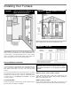
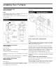

Installing Your Furnace
The following rules apply:
1. Use new, properly reamed pipe free from metal chips and
debris such as steel or black iron pipe. Use fittings approved
by local codes.
2. Do not thread pipe too far. Valve distortion or malfunction may
result from excess pipe within control. Apply moderate amount
of good quality dope to pipe only, leaving 2 end threads bare.
If LP Gas installation, use compound resistant to action of
liquefied petroleum gases.
3. Use ground joint unions.
4. Install a drip leg to trap dirt and moisture before it can enter
the gas valve. Drip leg must be a minimum of 3 inches long.
5. Install a manual shut-off valve.
6. Provide a 1/8" NPT test gauge connection immediately before
the gas supply connection to the furnace.
GAS CONNECTION
If installation is for L.P. Gas, have L.P. installer use two-stage
regulation and make all connections from storage tank to furnace.
Use two pipe wrenches when making the connection to the valve
to prevent turning or damage to gas valve.
Connections between the manual shutoff valve and burner control
assembly can be made with an A.G.A./C.G.A. design certified
flexible connector if allowed by local codes. Drip leg and ground
joint unions are still required.
Tighten all joints securely.
CHECKING THE GAS PIPING
Test all piping for leaks. When checking gas piping to the furnace
with gas pressure less than 1/2 PSI, shut off manual gas valve to
the furnace. If gas piping is to be checked with the pressure at or
above 1/2 PSI, the furnace and manual shut off valve must be
disconnected during testing. (SEE WARNING.) Apply soap
solution to each joint. Bubbles forming indicate a leak. Correct
even the slightest leak at once.
WARNING: Danger of property damage, bodily
injury or loss of life. Never use a match or open
flame to test for leaks. Never exceed specified
pressures for testing. High pressures may damage
the gas valve and cause over-firing which may
result in heat exchanger failure. Liquid petroleum
(L.P. Gas) is heavier than air and it will settle in any
low area, including open depressions and it will
remain there unless area is ventilated.
Never attempt startup of unit before thoroughly
ventilating area.
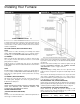
Electrical Wiring
The appliance, when installed, must be electrically grounded in
accordance with local codes, or in the absence of local codes,
with the National Electrical Code (ANSI/NFPA 70) or Canadian
Electrical Code (CSA C22.1), if an external electrical source is
utilized. This appliance is equipped with a three-prong (grounding)
plug for your protection against shock hazard and should be
plugged directly into a properly grounded three-prong receptacle.
Do not cut or remove the grounding prong from this plug.
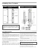
ELECTRICAL SUPPLY
Remove three-prong (grounding) service cord from the envelope
parts package to install in the furnace. Remove 7/8" diameter
(22mm) knockout at the left or right bottom side panel to route the
three-prong service cord to an electrical outlet.
1. Insert the nylon cap attached to the end of the three-prong
service cord thru the 7/8" diameter (22mm) knockout into the
burner control assembly area and insert it into the nylon plug
attached to the outer casing bottom. If desired, you may route
the thermostat wire alongside of the service cord and thru the
same opening or choose another entry into the burner control
assembly area.
2. Attach 7/8" diameter (22mm) strain relief around the three-
prong (grounding) service cord and the thermostat wire (if
thermostat wire is routed thru knock-out). Insert the 7/8"
(22mm) strain relief into the 7/8" (22mm) hole in the side panel
of furnace.
WARNING: Do not insert the three-prong
(grounding) service cord inside the burner control
assembly area more than 10 inches (245mm). This
could cause damage to the electrical cord resulting
in electrical shock hazard and/or fire.
LOW VOLTAGE CONNECTIONS
CAUTION: The Heat Anticipator will burnout if 24
volts are applied directly to thermostat by shorting
out the gas valve or primary control during testing
or by incorrect wiring.
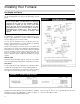
WALL THEMOSTAT WIRING
Run thermostat wire to the furnace. Connect thermostat to two
wires marked "Thermostat" extending from top of furnace, using
two wire nuts provided. See Wiling Diagrams on pages 30 or 31.
Replace fan to original position on motor shaft, tightening
securely. Replace fan shroud, making sure it is centered vertically
on the fan.
Tighten screws securely.
Replace top front panel and secure with thumbscrew.
COMPLETE WIRING DIAGRAMS ON PAGES 30 AND 31.
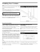
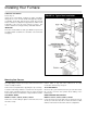
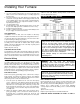
FIGURE 23 Gas Pipe Sizes
Btu/hr.
Btu/hr.