
Full Product Manual


Installing Your Furnace
22
MOUNTING
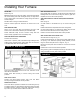
Refer to Fig. 29.
BEFORE placing the furnace into position, place Out Boot against
the furnace casing with inside of flanges exactly on edges of the
hole in casing. Mark hole locations on casing through the holes in
Out Boot flanges.
Drill #33 holes in casing at marked locations.
Remove knockout plate and knockouts for screws from Inner
Liner.
SIDE REGISTER ONLY
Secure a 1x1 inch wood strip (not included in this kit) to wall
surface next to side outlet as a backup for metal filler strips.
Fasten metal filler strips to side of furnace casing with front
surface exactly opposite front of wood backup strip.
SIDE AND REAR OUTLET REGISTERS
Place furnace in Position.
With furnace in position, pass outer Boot through Plastergrounds,
holding it firmly against furnace casing. Mark and cut off the end
of the Outer Boot flush with the wall surface.
Press Inner Boot against furnace Inner Liner, mark and cut off
flush with the wall surface.
Fasten Outer Boot securely to furnace casing with screws
provided.
SIDE OUTLET ONLY
Position Inner Boot against furnace Inner Liner and fasten
securely through all holes with screws provided.
REAR OUTLET ONLY
Place Inner Boot in position and fasten with screws along the top
and bottom edges only. Place Damper Assembly inside Inner Boot
and fasten with one (1) screw on each side. Thread chain through
key hole in clip on Outer Grille and attach the Bell end.
SIDE AND REAR OUTLETS
Place Outlet Grille into position, drill through the wall material and
Plasterground with a #33 drill bit, using the holes in grille as a
template and secure with screws provided.
VENT ENCLOSURE KIT INSTALLATION (SURFACE MOUNT
ONLY)
Refer to Fig. 30.
Cut Side Panels to fit between the top of furnace casing and
ceiling.
Fasten Side Panels to wall parallel to furnace casing sides.
Cut Front Panel height to fit. Note that the bottom edge of Front
Panel is notched to fit into the furnace casing recess.
Fasten Front Panel to Side Panels with screws provided.
SIDE CASING GRILLE KIT MODEL 6702
See clearances on Page 23, Fig. 31.
Locate marked opening(s) on outer furnace casing. Mark and cut
an opening 1 inch wider than opening already marked (1/2 inch
larger on all four sides) as shown on Page 13, Fig. 13.
Remove knockout plate and knockouts for screws from furnace
inner liner.
Fasten Boot to Inner Liner with screws provided.
Using holes in grille as a template, drill two (2) #33 holes in outer
casing and fasten securely with screws provided.
FIGURE 29 Side Register
FIGURE 30