GWA Series 2 Gas-Fired Water Boilers Boiler Manual Contents Page 1 Prepare boiler location........................................................ 2 2 Prepare boiler...................................................................... 6 3 Install water piping............................................................. 10 4 Install gas piping................................................................ 13 5 Field wiring........................................................................
GWA Series 2 Gas-Fired Water Boilers – Boiler Manual Read this first! Failure to adhere to the guidelines below can result in severe personal injury, death or substantial property damage. The boiler contains ceramic fiber and fiberglass materials. Use care when handling these materials per instructions on page 39 of this manual. Failure to comply could result in severe personal injury. When servicing boiler — 1. To avoid electric shock, disconnect electrical supply before performing maintenance. 2.
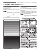
GWA Series 2 Gas-Fired Water Boilers – Boiler Manual 1 Prepare boiler location continued Clearances Service clearances Small space installations 1. Provide minimum clearances for cleaning and servicing the boiler and for access to controls and components as listed in the table below: 2. Provide at least screwdriver clearance to jacket front panel screws for removal of front panel for inspection and minor service.
GWA Series 2 Gas-Fired Water Boilers – Boiler Manual 1 Prepare boiler location continued Vent system Failure to follow all instructions can result in flue gas spillage and carbon monoxide emissions, causing severe personal injury or death. Inspect existing chimney before installing boiler. Failure to clean or replace perforated pipe or tile lining will cause severe personal injury or death. 2.
GWA Series 2 Gas-Fired Water Boilers – Boiler Manual 1 Prepare boiler location continued Air contamination Air openings Please review the following information on potential combustion air contamination problems. See Table 2 for products and areas which may cause contaminated combustion air. Combustion air and ventilation openings must comply with Section 5.3, “Air for Combustion and Ventilation”, of National Fuel Gas Code ANSI Z223.1–latest edition, or applicable local building codes.
GWA Series 2 Gas-Fired Water Boilers – Boiler Manual 1 Prepare boiler location Air openings continued continued Exhaust fans and air movers Motorized air dampers The appliance space must never be under a negative pressure. Always provide air openings sized not only to the dimensions required for the firing rate of all appliances, but also to handle the air movement rate of the exhaust fans or air movers using air from the building or space.
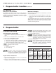
GWA Series 2 Gas-Fired Water Boilers – Boiler Manual 2 Prepare boiler continued Pressure test Perform hydrostatic pressure test Fill and pressure test Pressure test boiler before attaching water or gas piping or electrical supply (except as noted below). 1. Open the shutoff valves you installed on supply and return connections. 2. Slowly open boiler drain valve and fresh water supply to fill boiler with water. 3. When water flows from shutoff valves, close boiler drain valve. 4.
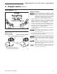
GWA Series 2 Gas-Fired Water Boilers – Boiler Manual 2 Prepare boiler continued Draft hood & spill switch Install vent piping Draft hood installation 1. Connect from draft hood or vent damper outlet to chimney or vent with same size vent connector. 2. Where possible, vertical venting to the outside from the draft hood or vent damper outlet will offer best performance. 3.
GWA Series 2 Gas-Fired Water Boilers – Boiler Manual 2 Prepare boiler Vent damper continued continued Damper installation Do not modify draft hood or vent damper, or make another connection between draft hood and vent damper or boiler except as noted below. This will void CSA certification and will not be covered by warranty. Any changes will cause severe personal injury, death or substantial property damage. 1.
GWA Series 2 Gas-Fired Water Boilers – Boiler Manual 3 Install water piping General If installation is to comply with ASME or Canadian requirements, an additional high temperature limit is needed. Install control in supply piping between boiler and isolation valve. Set second control to minimum 20 °F above setpoint of first control. Maximum allowable setpoint is 240 °F. See pages 21 & 22 for wiring.
GWA Series 2 Gas-Fired Water Boilers – Boiler Manual 3 Install water piping Near-boiler piping Figure 5 continued continued Use Figure 5 or Figure 6 only for systems designed for return water at least 130 °F. For systems with low return water temperature possible, such as converted gravity systems and radiant heating systems, install bypass piping (see page 12) to protect boiler against condensation.
GWA Series 2 Gas-Fired Water Boilers – Boiler Manual 3 Install water piping Near-boiler piping Figure 8 continued continued System bypass piping in boiler loop with separate system circulator, using primary/ secondary piping. Figure 9 Boiler bypass piping — use only for high water content systems —DO NOT use for radiant panel systems. System bypass method Boiler bypass method 1.
GWA Series 2 Gas-Fired Water Boilers – Boiler Manual 4 Install gas piping Connecting gas supply piping to boiler 1. Remove jacket front panel and see Figure 10 to pipe gas to boiler. a. Install drip leg at inlet of gas connection to boiler. Where local utility requires drip leg to be extended to the floor, use appropriate length of nipple between cap and tee. b. Install ground joint union for servicing, when required. c.
GWA Series 2 Gas-Fired Water Boilers – Boiler Manual 5 Field wiring For your safety, turn off electrical power supply at service entrance panel before making any electrical connections to avoid possible electric shock hazard. Failure to do so can cause severe personal injury or death. Wiring must be N.E.C. Class 1. If rollout thermal fuse element wire as supplied with boiler must be replaced, type 200 °C wire or equivalent must be used.
GWA Series 2 Gas-Fired Water Boilers – Boiler Manual 6 Start-up Preparation Check for gas leaks • • • • • Before starting the boiler, and during initial operation, smell near the floor and around the boiler for gas odorant or any unusual odor. Do not proceed with start-up if there is any indication of a gas leak. Repair any leak at once. Propane boilers only — Your propane supplier mixes an odorant with the propane to make its presence detectable.
GWA Series 2 Gas-Fired Water Boilers – Boiler Manual 6 Start-up continued Operate boiler DO NOT proceed with boiler operation unless boiler and system have been filled with water and all instructions and procedures of previous manual sections have been completed. Failure to do so could result in severe personal injury, death or substantial property damage. Before starting the boiler . . . • See manual Section 10 for spark-ignited pilot “Operating Instructions” procedure (see Table 6, below).
GWA Series 2 Gas-Fired Water Boilers – Boiler Manual 6 Start-up continued Verify operation 2. Vent air from system using manual vents. Air in the system will interfere with circulation and cause heat distribution problems and noise. 3. Inspect vent system thoroughly for signs of deterioration from corrosion, physical damage or sagging. Verify that masonry chimney liners are in good condition, with no obstructions, and there are no openings into the chimney. 4.
GWA Series 2 Gas-Fired Water Boilers – Boiler Manual 7 o o o o o Checkout procedure Boiler and heat distribution units filled with water? Automatic air vent, if used, open one full turn? Air purged from system? Air purged from gas piping? Piping checked for leaks? Correctly-sized manifold orifices installed? See Table 3, page 6, to check size and fuel type. Correctly sized manifold orifices must be used. Failure to do so will cause severe personal injury, death or substantial property damage.
GWA Series 2 Gas-Fired Water Boilers – Boiler Manual 8 Department of Energy – Compliance This boiler is equipped with a control system that automatically adjusts a time delay period to turn on the boiler during a call for heat. This is accomplished by circulating available hot water in the system while measuring water boiler water temperature changes.
GWA Series 2 Gas-Fired Water Boilers – Boiler Manual 9 Sequence of operation – spark-ignited pilot boilers 5. Thermostat satisfied (thermostat circuit opens) — Pilot and main gas valves are closed — Vent damper is deenergized, and cycles to closed position. Circulator is shut off. 6. Boiler is now in the standby mode. 7. Thermostat anticipator setting: Set thermostat heat anticipator as instructed in Figure 15b, page 22.
GWA Series 2 Gas-Fired Water Boilers – Boiler Manual 9 Sequence of operation – spark-ignited pilot boilers Figure 15a Schematic wiring diagram — Spark-ignited pilot system Part Number 550-142-784/0812 21
GWA Series 2 Gas-Fired Water Boilers – Boiler Manual 9 Sequence of operation – spark-ignited pilot boilers Figure 15b Schematic wiring diagram — Spark-ignited pilot system 22 Part Number 550-142-784/0812
GWA Series 2 Gas-Fired Water Boilers – Boiler Manual 10 Operating instructions – spark-ignited pilot boilers Gas valve — Honeywell VR8204 or VR8304 — White-Rodgers 36C or 36E FOR YOUR SAFETY READ BEFORE OPERATING If you do not follow these instructions exactly, a fire or explosion may result causing property damage, personal injury or loss of life. A. This appliance is equipped with an ignition device which automatically lights the pilot. Do not try to light the pilot by hand. B.
GWA Series 2 Gas-Fired Water Boilers – Boiler Manual 10 Operating instructions – spark-ignited pilot boilers Gas valve — Robertshaw 7200 24 Part Number 550-142-784/0812
GWA Series 2 Gas-Fired Water Boilers – Boiler Manual 11 Service and maintenance Table 6 Service and maintenance schedules (service technician and owner) Service technician Owner maintenance (see following pages for instructions) (see User’s Information Manual for instructions) o Inspect: o Daily • Reported problems • Check boiler area • Boiler area • Check boiler pressure/ temperature gauge • Air openings • Check air openings • Flue gas vent system • Pilot and main burner flames o Monthly •
GWA Series 2 Gas-Fired Water Boilers – Boiler Manual 11 Service and maintenance The boiler should be inspected and started annually, at the beginning of the heating season, only by a qualified service technician. In addition, the maintenance and care of the boiler designated in Table 6, page 25 and explained on the following pages must be performed to assure maximum boiler efficiency and reliability. Failure to service and maintain the boiler and system could result in equipment failure.
GWA Series 2 Gas-Fired Water Boilers – Boiler Manual 11 Service and maintenance o Service. . . . . . . . . . continued o Check/test. . . . . . . . . . Air vents and air elimination Oiled-bearing circulators 1. The circulator shipped with the GWA boiler is water-lubricated. No oiling is required. 2. Check other circulators in the system. Oil any circulators requiring oil, following circulator manufacturer’s instructions. Over-oiling will damage the circulator. Temperature sensor 1.
GWA Series 2 Gas-Fired Water Boilers – Boiler Manual 11 Service and maintenance o Check/test. . . . . . . . . . continued Diaphragm- or bladder-type — welded gas tight with a rubber membrane to separate the tank pressurizing air and the water. May be located at any point in the system, but most often found near the boiler. • Systems with this type of expansion tank require at least one automatic air vent, preferably located on top of an air eliminator, as shown in examples in Manual Section 3, page 10.
GWA Series 2 Gas-Fired Water Boilers – Boiler Manual 12 Troubleshooting Label all wires prior to disconnection when servicing controls. Wiring errors can cause improper and dangerous operation. Never jumper (bypass) rollout thermal fuse element or any other device except for momentary testing as outlined in Troubleshooting Charts. Severe personal injury, death or substantial property damage can result.
GWA Series 2 Gas-Fired Water Boilers – Boiler Manual 11 Troubleshooting – spark-ignited pilot boilers Temperature sensor The information on this page and pages 31 through 38 apply only to spark-ignited pilot GWA boilers. These boilers are equipped with an ignition control module that has indicator lights to show control status. See Charts 1 through 6, pages 32-38, help you identify problems based on indicator light conditions. 1. The boiler temperature sensor is a resistance-type device. 2.
GWA Series 2 Gas-Fired Water Boilers – Boiler Manual 11 Troubleshooting – spark-ignited pilot boilers Control indicator lights — HARD LOCKOUT Summary (Flashing LED’s) MAY remove 120VAC power for more than 2 seconds to clear lockout OR ignition control will automatically restart sequence of operation after 1 hour waiting period after fault condition is cleared. INDICATOR LIGHT CONDITION POWER Flashes once per second 120 VAC connection to boiler reversed.
GWA Series 2 Gas-Fired Water Boilers – Boiler Manual 12 Troubleshooting – spark-ignited pilot boilers Figure 17 Control module connections 32 Part Number 550-142-784/0812
GWA Series 2 Gas-Fired Water Boilers – Boiler Manual 12 Troubleshooting – spark-ignited pilot boilers CHART 1 — Spark-ignited pilot — Troubleshooting POWER light status — Usually indicates reversed 120 VAC polarity if POWER light flashes by itself — Electrical shock hazard — Wherever you see TURN OFF POWER, follow the instructions. Failure to follow instructions could result in severe personal injury, death or substantial property damage. Is POWER light off? No • Yes • • Is POWER light...
GWA Series 2 Gas-Fired Water Boilers – Boiler Manual 12 Troubleshooting – spark-ignited pilot boilers CHART 2 — Spark-ignited pilot — TSTAT CIRC & POWER lights flashing — Usually indicates 48 VAC on thermostat circuit (stray voltage) — Electrical shock hazard — Wherever you see TURN OFF POWER, follow the instructions. Failure to follow instructions could result in severe personal injury, death or substantial property damage.
GWA Series 2 Gas-Fired Water Boilers – Boiler Manual 12 Troubleshooting – spark-ignited pilot boilers CHART 3 — Spark-ignited pilot — DAMPER light flashing — If POWER light is flashing: Usually indicates vent damper failed to prove open within 5 minutes — — If POWER light is steady: Usually indicates vent damper closed during run cycle — Electrical shock hazard — Wherever you see TURN OFF POWER, follow the instructions.
GWA Series 2 Gas-Fired Water Boilers – Boiler Manual 12 Troubleshooting – spark-ignited pilot boilers CHART 4 — Spark-ignited pilot — FLAME & POWER lights flashing — Usually indicates flame sensed when it shouldn't be there — Electrical shock hazard — Wherever you see TURN OFF POWER, follow the instructions. Failure to follow instructions could result in severe personal injury, death or substantial property damage.
GWA Series 2 Gas-Fired Water Boilers – Boiler Manual 12 Troubleshooting – spark-ignited pilot boilers CHART 5 — Spark-ignited pilot — FLAME light flashing and POWER light on steady ALSO — Troubleshooting failure to establish main flame Electrical shock hazard — Wherever you see TURN OFF POWER, follow the instructions. Failure to follow instructions could result in severe personal injury, death or substantial property damage.
GWA Series 2 Gas-Fired Water Boilers – Boiler Manual 12 Troubleshooting – spark-ignited pilot boilers CHART 6 — Spark-ignited pilot — Insufficient heat or no heat (POWER light on steady) Electrical shock hazard — Wherever you see TURN OFF POWER, follow the instructions. Failure to follow instructions could result in severe personal injury, death or substantial property damage. • Has it been at least 5 minutes since setting thermostat to call for heat? If not, wait 5 minutes.
GWA Series 2 Gas-Fired Water Boilers – Boiler Manual Handling ceramic fiber and fiberglass materials REMOVAL OF COMBUSTION CHAMBER LINING OR BASE PANELS The combustion chamber lining or base insulation panels in this product contain ceramic fiber materials. Ceramic fibers can be converted to cristobalite in very high temperature applications.
GWA Series 2 Gas-Fired Water Boilers – Boiler Manual 13 Replacement parts Figure 18 Section assembly, flue collector, draft hood and vent damper Item number Description not shown Replacement section assembly 1 Radiation plate (1 per joint) 2 Collector hood 3 40 Drafthood Part number GWA-052 GWA-070 GWA-105 GWA-140 GWA-175 GWA-210 GWA-245 321-114-345WT 321-114-345WT 321-114-346WT 321-114-347WT 321-114-348WT 321-114-349WT 321-114-350WT Item number 4 Description Part number Temperature sensor
GWA Series 2 Gas-Fired Water Boilers – Boiler Manual 13 Replacement parts continued Figure 19 Base assembly, manifold, orifices and burners Item number Description Base assembly kit Part Number 550-142-784/0812 Part number GWA-052 GWA-070 GWA-105 GWA-140 GWA-175 GWA-210 GWA-245 381-354-355WT 381-354-356WT 381-354-357WT 381-354-358WT 381-354-359WT 381-354-360WT 381-354-361WT 1 Base side panel (in Base assembly) 2 Base front cross-tie assembly (in Base assembly) 3 Base back cross-tie assembly (in
GWA Series 2 Gas-Fired Water Boilers – Boiler Manual 13 Replacement parts continued Figure 20 Jacket assembly Item number Description Part number Part number 1 Junction box, 2 x 4 (Available at local supply house) 2 Jacket panel, left side with insulation GWA-052 GWA-070 GWA-105 GWA-140 GWA-175 GWA-210 GWA-245 3 Jacket panel, right side with insulation GWA-052 GWA-070 GWA-105 GWA-140 GWA-175 GWA-210 GWA-245 431-223-572WT 431-223-574WT 431-223-576WT 431-223-578WT 431-223-580WT 431-223-582WT 4
GWA Series 2 Gas-Fired Water Boilers – Boiler Manual 13 Replacement parts continued Figure 21 Trim assembly Item number 1 Description Manufacturer Manufacturer’s Part number Part number Pressure relief valve, ASME, 30 PSIG, ¾” male inlet Watts M330 511-546-920WT Pressure relief valve, ASME, 30 PSIG, ¾” female inlet (Fittings shown are factory-installed on boiler.
GWA Series 2 Gas-Fired Water Boilers – Boiler Manual 13 Replacement parts continued Figure 22 Gas control assembly Boiler model Manufacturer Manufacturer’s part number Part number Gas valve, ½” x ½” GWA-052 through GWA-175 GWA-210 through GWA-245 VR8204A2001 36E-266 7200IPER VR8304M4348 36C74-474 511-044-381WT Gas valve, ¾” x ¾” Honeywell White-Rodgers Robertshaw Honeywell White-Rodgers Item Description number Natural gas components 1 2 Pilot kit w/orifice & aluminum pilot gas tubing Willia
GWA Series 2 Gas-Fired Water Boilers – Boiler Manual 14 Dimensions Figure 23 Dimensional drawing — ALL DIMENSIONS IN INCHES Boiler model number Return Supply tappings tappings (inches NPT) (inches NPT) Gas connection & manifold size (Note 3) (inches NPT) “A” Vent location (inches) “D” Vent diameter (inches) “W” Jacket width (inches) “H” Damper height (inches) 5 4 10 45⅜ GWA-052 1¼ 1¼ ½ GWA-070 1¼ 1¼ ½ 5 4 10 52⅜ GWA-105 1¼ 1¼ ½ 6½ 5 13 54⅜ GWA-140 1¼ 1¼ ½ 8 6 16 57⅞
GWA Series 2 Gas-Fired Water Boilers – Boiler Manual 15 Ratings DOE Boiler model number 0-2,000 feet altitude Input (Btuh) (Note 3) DOE Heating Capacity (Output)(Btuh) (Note 1) 2,000-4,500 feet altitude Input (Btuh) Output (Btuh) (Note 4) Net AHRI ratings (Btuh) DOE Boiler Seasonal efficiency water (% A.F.U.E.) content (gallons) N-L (Note 2) Chimney and breeching size (Note 3) GWA-052 52,000 43,000 46,800 37,400 37,000 1.5 83.0 4”I.D.
GWA Series 2 Gas-Fired Water Boilers – Boiler Manual 16 Notes Part Number 550-142-784/0812 47
GWA Series 2 Gas-Fired Water Boilers – Boiler Manual W-T 8201 W. Calumet Rd.