
Operating instructions


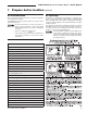


Boiler model
number
To
system
From
system
GWA-052
¾" ¾"
GWA-070
1" 1"
GWA-105
1" 1"
GWA-140
1" 1"
GWA-175
1¼" 1¼"
GWA-210
1¼" 1¼"
GWA-245
1½" 1½"
10
Part Number 550-142-784/0812
GWA
Series 2 Gas-Fired Water Boilers – Boiler Manual
3 Install water piping
Water piping — multiple zone systems
Installsystempipingusingeithercirculatorzoningorzonevalve
zoning.Installexpansiontankonsuctionsideofsystemcircula-
tor.Alwaysconnectlllineonlyattheexpansiontank—neverat
another point in the system.
Circulator
The circulator is shipped loose (wiring pre-attached to boiler)
to allow you to locate it either in the return or supply piping, as
desired. See page 11foratypicalinstallation.Pipetheexpansion
tanktothesuctionsideofthecirculatorwheneverpossible.Install
anairseparatorinthesupplypiping.Connecttheexpansiontank
totheairseparatoronlyiftheseparatorisonthesuctionsideof
thecirculator.Alwaysinstallthesystemllconnectionatthesame
pointastheexpansiontankconnectiontothesystem.Figures5
and 6 show typical near-boiler piping connections.
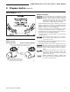
Expansion tank
Diaphragm-type or bladder-type expansion tank —
Figure 5
1. Ensure expansion tank size will handle boiler and system
watervolumeandtemperature.Tankmustbelocatedinboiler
returnpipingasclosetoboileraspossible,beforeinletside
ofcirculator.Seetankmanufacturer’sinstructionsfordetails.
2. Installanautomaticairventasshown.
Closed-type expansion tank — Figure 6
1. Ensureexpansiontanksizewillhandleboilerandsystemwater
volumeandtemperature.Seetankmanufacturer’sinstructions
fordetails.
2. Connecttankto½”NPTtappinglocatedbehindsupplyoutlet,
using ½” NPT piping. Pitch any horizontal piping up towards
tank1inchper5feetofpiping.
Undersizedexpansiontanks causesystem water
tobelostfromreliefvalveandmakeupwatertobe
addedthroughllvalve.Eventualsectionfailurecan
result.
Near-boiler piping continued
General
IfinstallationistocomplywithASMEorCanadianrequirements,
anadditionalhightemperaturelimitisneeded.Installcontrolin
supply piping between boiler and isolation valve. Set second
controltominimum20°Fabovesetpointofrstcontrol.Maximum
allowable setpoint is 240 °F. See pages 21 & 22forwiring.
Alowwatercutoffdeviceisrequiredwhenboilerisinstalledabove
radiation level or by certain state or local codes or insurance
companies.Uselowwatercutoffdesignedforwaterinstallations.
Electrodeprobe-typeis recommended.Purchase andinstallin
tee supply piping above boiler.
Usebackowcheckvalveincoldwatersupplyifrequiredbylocal
codes.
See Table 4 and Figure 5 (diaphragm-type or bladder-type
expansion tank) or Figure 6 (closed-type expansiontank) on
page 11 fornear-boiler piping for systems designed for return
water at least 130 °F.
See page 12, (Figures 8 and 9)fornear-boilerpipingforlow-
temperature or high-volume systems.
See page 11, (Figure 7)forboilersusedwithrefrigerationsystems.
Near-boiler piping
Isolation valves
Isolationvalvesarerequiredtoenableservicingoftheboiler’stem-
peraturesensor.Installasshowninappropriatepipingdiagram.
Relief valve
Installreliefvalveverticallyin¾”tappingonsideofboiler.See
thetagattachedtothereliefvalveformanufacturer’sinstructions.
To avoid water damage or scalding due to valve
operation, discharge line must be connected to re-
liefvalveoutletandruntoasafeplaceofdisposal.
Terminate the discharge line to eliminate possibility
ofsevereburnsshouldthevalvedischarge.
• Dischargelinemustbeasshortaspossibleandbe
the same size as the valve discharge connection
throughout its entire length.
• Dischargelinemustpitchdownwardfromthevalve
and terminate at least 6” above the floor drain where
any discharge will be clearly visible.
• Thedischargelineshallterminateplain,notthread-
ed,withamaterialserviceablefortemperaturesof
375 °F or greater.
• Donotpipethedischargetoanyplacewherefreez-
ing could occur.
• Noshutoffvalveshallbeinstalledbetweentherelief
valve and boiler, or in the discharge line. Do not plug
or place any obstruction in the discharge line.
• Failuretocomplywiththeaboveguidelinescould
resultinfailureofthereliefvalvetooperate,result-
inginpossibilityofseverepersonalinjury,deathor
substantial property damage.
• Testtheoperationofthevalveafterllingandpres-
surizingsystembyliftingthelever.Makesurethe
valvedischargesfreely.Ifthevalvefailstooperate
correctly,replaceitwithanewreliefvalve.
Table 4 Water pipe size (based on 20 °F rise)