
Operating instructions


12
Part Number 550-142-784/0812
GWA
Series 2 Gas-Fired Water Boilers – Boiler Manual
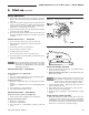
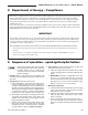
Figure 9 Boiler bypass piping — use only for high
water content systems —DO NOT use for
radiant panel systems.
Near-boiler piping continued
Installallcomponentsspeciedaboveandadjustvalvesasdescribedtopreventlowtemperatureintheboiler.Failureto
preventlowwatertemperatureintheboilercouldcausecorrosionoftheboilersectionsorburners,resultinginsevere
personal injury, death or substantial property damage.
3 Install water piping continued
Boiler bypass method
1. ApplybypasspipingofFigure9tohighwatercontentsystems,
such as converted gravity systems.
2. The bypass arrangement shown protects the boiler from
damage caused by condensate corrosion due to low return
water temperature. This method does not provide protection
fromhightemperaturewaterbeingsuppliedtothesystem.
3. DO NOT apply this piping to radiant panel systems.
4. Adjustthebypassvalvesasindicatedbelow.
Adjust Bypass valves 1 and 2 as follows:
1. Startwithvalve1fullyclosed,valve2fullyopen.
2. Slowlyopenvalve1whileclosingvalve2.Adjustthevalvesuntil
theboilerpressure/temperaturegaugereadsapproximately60
°Fhigherthanthesystemtemperaturegauge.Asyouopen
the valves, pause long enough to allow temperatures to level
off.Ittakesawhilefortheboilerwatertemperaturetoriseas
the flow changes.
3. Bypass valve 1 controls system flow rate. Bypass valve 2
controls flow through the boiler.
4. The purpose of this piping is to cause a high enough
temperature rise in the boiler that the average temperature
willbewarmenoughtopreventcondensationofuegases.
System bypass method
1. ApplybypasspipingofFigure 8 to high water content systems,
radiantpanelsystemsoranysystemthatislikelytooperate
withlowreturnwatertemperatureforextendedperiods.
2. The bypass arrangement shown protects the boiler from
damage caused by condensate corrosion due to low return
watertemperatureandprotectslowtemperaturesystemsfrom
too high a supply temperature.
3. Adjustthebypassvalvesasindicatedbelow.
Adjust Bypass valves 1 and 2 as follows:
1. Startwithvalve2fullyclosed,valve1fullyopen.
2. Slowlyopenvalve2whileclosingvalve1.Adjustthevalves
until the boiler pressure/temperature gauge reads 160 °F or
higher.Asyouopenthevalves,pauselongenoughtoallow
temperaturestoleveloff.Ittakesawhilefortheboilerwater
temperature to rise as the flow changes.
3. Bypass valve 2 allows hot boiler outlet water to blend with
colder return water, raising the supply temperature to the boiler.
Bypass valve 1 balances the pressure drop through valve 2.
4. Thepurposeofthispipingistoraisethereturnwatertemperature
totheboilerenoughtopreventcondensationofuegases.
Figure 8 System bypass piping in boiler loop with
separate system circulator, using primary/
secondary piping.