
Operating instructions


14
Part Number 550-142-784/0812
GWA
Series 2 Gas-Fired Water Boilers – Boiler Manual
5 Field wiring
Foryoursafety,turnoffelectricalpowersupplyat
serviceentrancepanelbeforemakinganyelectrical
connectionstoavoidpossibleelectricshockhazard.
Failure to do so can cause severe personal injury
or death.
WiringmustbeN.E.C.Class1.
If rollout thermal fuse element wire as supplied
withboilermustbereplaced,type200°Cwireor
equivalentmustbeused.Ifotheroriginalwiringas
supplied with boiler must be replaced, use only type
105°Cwireorequivalent.
Boiler must be electrically grounded as required by
NationalElectricalCodeANSI/NFPA70–latestedition.
Electrical installation must comply with:
1. NationalElectricalCodeandanyothernational,state,provin-
cial or local codes or regulations.
2. InCanada,CSAC22.1CanadianElectricalCodePart1,and
any local codes.
Wiring connections
Boiler is shipped with controls completely wired, exceptspill
switch and vent damper. See wiring diagram on pages 21 & 22
forspark-ignitedpilotboiler.Circulatorisshippedloose,butwiring
harnessispre-attachedtotheboiler.Connectwiresincirculator
junctionbox.
Thermostat
1. Connectthermostatasshownonwiringdiagramonboiler.
2. Installoninsidewallawayfrominuencesofdrafts,hotorcold
waterpipes,lightingxtures,television,sunraysorreplaces.
3. If thermostat has a heat anticipator, set heat anticipator
in thermostat to match power requirements of equipment
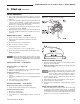
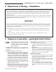
Figure 11 Field wiring connections — service switch, DHW (if used) and thermostat (or end switch) provided by installer.
connectedtoit.Ifconnecteddirectlytoboiler,setfor0.4amps.
Forotherdevices,seemanufacturer’sspecications.Wiring
diagramonboilergivessetting forcontrol moduleandgas
valve.Alsoseeinstructionswiththermostat.
DHW (if used)
ConnectDHWaquastatasshowninwiringbelow.Economy
functionisn’tutilizedwithDHWinput.
R & C Connections (if used)
24Vacleadsshouldbeusedforpowerstealingthermostatsonly!
Junction box (furnished)
1. Connect120VACpowerwiring(Figure11).
2. Fused disconnect or service switch (15 amp. recommended)
maybemountedonthisbox.Forthoseinstallationswithlocal
codeswhichprohibitinstallationoffuseddisconnectorservice
switchonboiler,installa2x4coverplateontheboilerjunction
boxandmounttheserviceswitchremotelyasrequiredbythe
code.
Wiring multiple zones
Seezonevalvemanufacturer’sliteratureforwiringandapplication.
Aseparatetransformerisrequiredtopowerzonevalves.Zoning
withcirculatorsrequiresarelayforeachcirculator.
DO NOT connect directly from 3-wire zone
valves to the T-T terminals on the boiler
.
When using 3-wire zone valves, install an isolation
relay.Connectthezonevalveendswitchwiresto
theisolationrelaycoil.Connecttheisolationrelay
contact across the boiler T-T terminals. Failure to
comply can result in damage to boiler components
or cause unreliable operation, resulting in severe
property damage.