
Operating instructions


30
Part Number 550-142-784/0812
GWA
Series 2 Gas-Fired Water Boilers – Boiler Manual
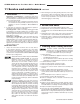
Figure 16 GWA Ignition cntrol module
11 Troubleshooting – spark-ignited pilot boilers
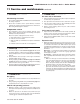
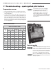
Sensor resistance values
Temp
(°F)
Sensor ohms
Temp
(°F)
Sensor ohms
Min Max Min Max
32
34265 37871
120
4517 4992
40
27834 30764
130
3698 4088
50
21630 23907
140
3043 3364
60
16944 18727
150
2517 2782
70
13372 14780
160
2091 2311
80
10629 11747
170
1744 1928
90
8504 9399
180
1461 1615
100
6847 7568
190
1229 1359
110
5545 6129
200
1038 1147
Temperature sensor
1. The boiler temperature sensor is a resistance-type device.
2. The Chartbelowshowsthecorrectvalueforthesensorat
various temperatures.
3. Usetheresistancevaluesat32°F,60°F,70°Fand212°Fto
measurethesensorresistanceatknowntemperatures(ice
point, room temperature and sea level boiling point). For ice
point and boiling point, insert the sensor in water at that tem-
perature.Useanohmmetertoreadresistancevaluebetween
thermister # and thermistor common. See Figure 30, page 50,
forsensorplugdetails.
Sensor resistance values
Theinformationonthispageandpages
31 through 38applyonlytospark-ignited
pilotGWAboilers.Theseboilersare
equipped with an ignition control module
that has indicator lights to show control
status. See Charts 1 through 6, pages 32-38,
helpyouidentifyproblemsbasedonindicator
light conditions.
Control module
Solder or water splatter between plugs and circuit
board can cause improper operation of control
module. Place a shield over the boiler internal
controls and components during installation.
Failure to comply could result in severe personal
injury, death or substantial property damage.
Makesureground wiring is installed per wiring
diagram.Goodgroundingisextremelyimportant
forproperoperation.