
Operating instructions


8
Part Number 550-142-784/0812
GWA
Series 2 Gas-Fired Water Boilers – Boiler Manual
1. Connectfromdrafthoodorventdamperoutlettochimneyor
vent with same size vent connector.
2. Wherepossible,verticalventingtotheoutsidefromthedraft
hoodorventdamperoutletwillofferbestperformance.
3. Where horizontal vent connector is used, slope upward at
least¼”perlinealfoottowardchimneyorventandsupport
with hangers to prevent sagging.
4. Breechingmustnotbeconnectedtoanyportionofamechanical
draft system that can operate under positive pressure.
Longhorizontalventconnector,excessivenumber
ofelbowortees,orotherobstructionsthatrestrict
theowofcombustiongases should be avoided.
Severe personal injury, death or substantial property
damage could result.
Install vent piping
These systems are used on gas-fired boilers with
ventdampersasshippedfromfactory.Boilerwillnot
operate without vent damper installed.
Only vent dampers listed in the Replacement parts
list on Page 40arecertiedforusewithGWAboil-
ers.Anyotherventdamperinstalledcouldcause
severe personal injury or death.
Damper blade
Standing pilot ignition systems— See vent manufacturer’s
instructions to install plug (shipped with damper) in damper hole.
For standing pilot boilers only, install plug with
3
/8” diameter hole
in vent damper hole.
Spark-ignited pilot systems— See vent manufacturer’s
instructions to install plug (shipped with damper) in damper hole.
For spark-ignited pilot boilers only, install plug with no hole in
vent damper hole.
Minimum clearances
Provide a minimum of 6” between the ventdamper and any
combustiblematerial.(See“Minimumclearancetocombustible
materials,” page 3,forminimumclearancefromjackettoptoceiling
to maintain this dimension.)
Vent damper
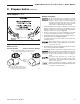
Draft hood installation
1. Orientdrafthoodwithspillswitchmountingholestofrontof
boiler as shown in Figure 3.
2. Securedrafthoodtooutletattopofboilerwithsheetmetal
screws.
Draft hood & spill switch
3. Bottomofdrafthoodorskirt must have clearance dimension
abovejackettoppanelasindicatedondrafthood.
Donotalterboilerdrafthoodorplaceanyobstruction
or non-approved vent damper in breeching or vent
system.CSAcerticationwillbecomevoid.Fluegas
spillageandcarbonmonoxideemissionswilloccur
causing severe personal injury or death.
Improper orientation of spill switch may cause
boilertoshutdown.Thelossofheatcanresultin
signicantdamageduetofreezing.
Spill switch installation
1. FastenspillswitchtodrafthoodasshowninFigure 3.
2. See Wiring diagram to connect wires:
Spark-ignitedpilotboiler—seepages 21 & 22.
2 Prepare boiler continued
Figure 3 Spill switch with wire harness