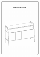
Assembly Instructions P.
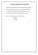
r General Assembly Guidelines I. Ensure that all parts and hardware are available before beginning assembly. II. Follow each step carefully to ensure the proper assembly of this product. Ill. Two people are recommended for ease in the assembly of this product. IV. The main type of hardware used to assemble this product is: bolts. V. Power tools should not be used to assemble this product . \. P.
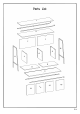
Parts List 1 17 10 2 7 7 0, 5 : 6 11 12 4 13 14 15 P.
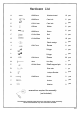
Hardware List A � 08x3Omm Wooden dowel 12 pcs B m 08x35mm Cam bolt 6 pcs 015x11mm Cam lock 6 pcs 030mm Sticker 6 pcs 06x5Omm Screw 6 pcs 01/4x12mm Bolt 8 pcs 01/4x25mm Bolt 16 pcs Plastic wedge 8 pcs Screw 8 pcs Hinge 4 pcs Hinge 4 pcs 03x14mm Screw 32 pcs 4mm Hex Key 1 pc 08x5x16mm Shelf support pin 8 pcs Glue tube 1 pc L shape Bracket 2 pcs Screw 2 pcs Anchor 2 pcs Washer 2 pcs � C 0 D E � ®-» @-mm» F G H � J K L M N p Q R s T
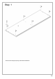
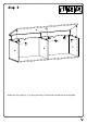
: B Step 1 色B_ _ _ _ _ _ _ _______* o B : 心 令B_ _ _ _ _ _ _ _ j iI I B 2 eB_ _ _ _ _ _ _ _ { I I I ) I I I I 门』; 0j Secure cam bolt (B) to part (2) with head screwdriver. P.
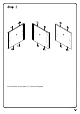
Insert wooden A) into part (4, 5, 6) as per diagram.
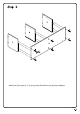
Attach part (3) to part (4, 5, 6) using screw (E) with hex key (N) as per diagram.
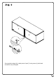
Slide part (7) into grooves of part (4, 5, 6) as per diagram.
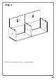
Attach part (2) to part (4, 5, 6) using cam lock (C) with head screwdriver as per diagram.
Secure plastic wedge (H) to back panel of part (7) using screw (J) with head screwdriver as per diagram.
Attach part (9, 10) to part (3) using bolt (F, G) with hex key (N) as per diagram.
Attach L shape bracket (R) to part (17) with hex key (N) as per diagram. Attach part (17, 10) to part (1) using bolt (F, G) with hex key (N) as per diagram.
Attach part (11) to part (4, 9, 10, 17) using bolt (G) with hex key (N) as per diagram.
Attach part (12) to part (5, 9, 10, 17) using bolt (G) with hex key (N) as per diagram.
Insert shelf support pin (P) into part (4, 5, 6) as per diagram.
Place part (8) on top of shelf support pin (P).
Attach hinge (L) to part (14, 15) using screw (M) with head screwdriver as per diagram.
Attach hinge (K) to part (16, 13) using screw (M) with head screwdriver as per diagram.
Attach hinge (K) and part (13) to part (4) using screw (M) with head screwdriver as per diagram.
Attach hinge (L) and part (14) to part (6) using screw (M) with head screwdriver as per diagram.
Attach hinge (L) and part (15) to part (6) using screw (M) with head screwdriver as per diagram.
Attach hinge (K) and part (16) to part (5) using screw (M) with head screwdriver as per diagram.
1. Place unit in desired location and mark the wall for anchor location, drill hole using 6mm size bit. 2. Insert anchor (T) into wall at desired location. 3. Secure furniture to wall using L shape bracket (R) and screw (R) per diagram.
Step 20 Final Assembly P.