
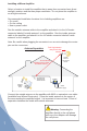
User's Manual


Amplifi er Specifi cations
Model Number 274106
Connectors N-Female 50 ohms
Impedance (input/output) 50 Ohms
Dimensions 4.5 x 3.5 x 1.25 inch (11.4 x 8.9 x 3.2 cm)
Weight 1.5 lbs (0.7 kg)
Frequency 896-940 MHz
¹Passband Gain (nominal)
70 dB Maximum
²20 dB Bandwidth (nominal)
Uplink/Downlink 45 MHz / 46 MHz Maximum
Power output for single cell phone (uplink)
iDEN +20.9 dBm
³Power output (uplink for multiple cell
phones:
Number of
cell phones
4
Maximum Power
2 +22.1 dBm
3 +18.6 dBm
4 +16.1 dBm
5 +14.1 dBm
6 +12.6 dBm
Power output for single received channel (downlink)
iDEN +19.8 dBm
³Power output for multiple received
channels (downlink)
4
Maximum Power
The maximum power is reduced by the
number of channels:
Number of
cell phones
2 +22.9 dBm
3 +19.4 dBm
4 +16.9 dBm
5 +14.9 dBm
6 +13.4 dBm
Noise Figure (typical) 3 - 4 dB
Isolation (uplink/downlink) >90 dB
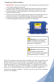
Power Requirements 120 V AC, 0.2 A
FCC ID: PWO274106SB
IC: 4726A-274106SB
Notes:
1. Nominal gain is the maximum gain at any frequency in the passband.
2. Nominal bandwidth is the difference between two frequencies that are adjacent to the passband where the amplifi cation is 20 dB
lower than the passband amplifi cation. One of the frequencies is lower than the passband and the other is higher.
3. The Manufacturer’s rated output power of this equipment is for single carrier operation. For situations when multiple carrier
signals are present, the rating would have to be reduced by 3.5 dB, especially where the output signal is re-radiated and can
cause interference to adjacent band users. This power reduction is to be by means of input power or gain reduction and not by
an attenuator at the output of the device.
4. The maximum power for 2 or more simultaneous signals will be reduced by 6 dB every time the number of signals is doubled.
Wilson
®
Electronics, Inc.
3301 East Deseret Drive, St. George UT 84790
For additional Technical Support visit
www.wilsonelectronics.com
Phone: 866-294-1660 Fax: 435-656-2432
Part #000000 AIG IB900i 006 / 05.23.07