
User's Manual


4
Installation Overview
The following steps provide a summary of the amplifi er/antenna installation
process. However, they are not a substitute for the complete installation
instructions on the following pages, which you should read thoroughly. Contact
Wilson’s Technical Support Department with any questions at 866-294-1660.
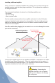
STEP 1 Install the Outside Antenna
Mount the Yagi antenna so that it points toward the cell site and away from
where the inside antenna will be located. The two antennas will need 75 feet of
separation. (See illustrations on pages 5 and 7.)
STEP 2 Install the Inside Antenna
Select a location in the center of where the signal needs to be amplifi ed. Refer
to the instructions included with the inside antenna. (See illustration on page 6 to
determine the inside antenna model that best meets your specifi c needs.)
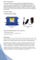
STEP 3 Install the Amplifi er
Position the amplifi er in a well-ventilated location near a power outlet. Attach the
outside and inside antennas to the amplifi er using 9913 or equivalent coax cable
(available from Wilson Electronics).
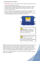
STEP 4 Power up the Amplifi er
IMPORTANT! Before connecting the power supply, ensure that both the inside
and outside antenna cables are connected. Also ensure that all cell phones and
cellular data cards within 50 feet of the inside antenna are turned off. Plug in the
supplied 6-volt power supply into the amplifi er and then into a wall outlet.
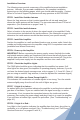
STEP 5 Check the Amplifi er Lights
The PWR light should be green, indicating that the amplifi er has power. If all
other lights are also green, the amplifi er is operating properly; however, if you do
not have the desired signal coverage area, refer to pages 5, 6, 9 and 10. (Note: if
you are using an outdoor Yagi antenna, it must be adjusted for maximum signal.)
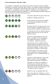
STEP 6 If All Lights are Green Except Light D…
This indicates the combination of outside signals is too strong. Turn the outside
antenna slightly away from the cell site until all lights are green.
STEP 7 If Light A is Amber…
An amber light in the A position indicates the amplifi er is working but at reduced
gain due to oscillation. If you are satisfi ed with the signal coverage, no action
is necessary. If not, increase the separation between the inside and outside
antennas, then unplug the power supply and plug it back in to reset the amplifi er.
If you still have an amber light, repeat the procedure. (See “Troubleshooting” on
page 10.)
STEP 8 If Light A is Red…
A red light in the A position indicates the amplifi er has shut down, due either to
oscillation or to cell phone overload. (See “Troubleshooting” and “Cell Phone
Overload Protection” on pages 10 and 11.)