Channelized 800 MHz Adjustable Gain In-Building Wireless Smart Technology ™ Signal Boosters Contents: Antenna Options & Accessories . . . . . . . . . . . . . . . . . . . . . . . . . . . . . . . 1 Quick Install Overview. . . . . . . . . . . . . . . . . . . . . . . . . . . . . . . . . . . . . . . 2 Installation Diagram. . . . . . . . . . . . . . . . . . . . . . . . . . . . . . . . . . . . . . . . .
Installation Instructions for the Following Wilson Electronic Signal Booster: Channelized 800 MHz Adjustable Gain In-Building Wireless Smart Technology ™ Signal Booster Model # 277180 FCC ID: PWO277180 IC: 4726A-277180 The term “IC” before the radio certification number only signifies that Industry Canada technical specifications were met.
Quick Install Overview See Installation Diagram on page 3. Contact Wilson Electronics Technical Support Team with any questions at 866-294-1660. 1. Select a location to install the Signal Booster that is away from excessive heat, direct sunlight, moisture and has proper ventilation. Do not place the Signal Booster in an air-tight enclosure. 2. Select a location on the roof of the building to install the Outside Antenna. Use a cell phone in test mode to find the strongest signal from the cell tower.
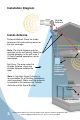
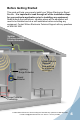
Installation Diagram Outside Antenna Inside Antenna Preferred Method: Place the Inside Antenna in the ceiling facing down for the best coverage. Note: The Inside Antenna may be mounted on the wall directly under the Outside Antenna, in the null zone, if 20 feet of vertical separation can be maintained. Null Zone: The area under the Outside Antenna, where the Outside Antenna radiates the least. Note: A Lightning Surge Protector is recommended for all building installations (sold separately).
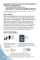
Before Getting Started This guide will help you properly install your Wilson Electronics Signal Booster. It is important to read through all of the installation steps for your particular application prior to installing any equipment. Read through the instructions, visualize where all the equipment will need to be installed and do a soft installation before mounting any equipment. Contact Wilson Electronics Technical Support with any questions at: 866-294-1660.
Reasons for Weak Cellular Signals Anyone who uses a cell phone or cellular data card knows the frustration of not being able to connect to or maintain a strong cellular signal. When this occurs, it is generally due to one of two reasons: 1.
Cell Signal Outside Wide Band Antenna Cell Tower Signal readings usually appear as a negative number (for example, -86). The closer you get to zero the stronger the signal. (See graph below). Signal Strength Graph EXCELLENT -50dB -60dB GOOD -70dB -80dB POOR -90dB -100dB NO SIGNAL -110dB Selecting a Direction for the Outside Antenna Before selecting a location on the roof of the building to install the Outside Antenna, see page 8 for additional instructions.
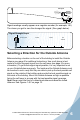
Drip hole on bottom Cell Tower Outside Antenna Installation The antenna should be mounted as shown in the illustration above. The mounting bracket, included with antenna, is adjustable and will accommodate pipe diameters from 1.25” to 2” (pipe sold separately). Mount the antenna so that there is at least 3 feet of clearance in all directions around it. Position the antenna so that it has an unobstructed line of sight to the cell tower’s strongest signal.
Mounting Tips for Running Outside Antenna Cable If you are mounting the Outside Antenna on the roof of your building, we have found that it is easiest to run your cable underneath the down side of your roof’s flashing. If you have satellite TV service installed you may be able to follow the same route as the satellite TV cables that are already running from outside of your building to the inside.
In some cases, multiple Inside Antennas may be required, for instance if you have multiple rooms with poor signal. A signal may be split by using a splitter (sold separately). If using more than one Inside Antenna, a separation up to 75 horizontal feet may be necessary between Inside Antennas. See configuration on pages 3 & 4.
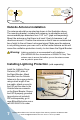
Figure 1 CORRECT INSTALLATION Point antennas away from each other Outdoor Antenna Inside Panel Antenna Signal Booster Figure 2 INCORRECT INSTALLATION Never point antennas toward each other Outdoor Antenna Inside Panel Antenna Signal Booster Contact Wilson Electronics Technical Support Team with any questions at 866-294-1660 or email: tech@wilsonelectronics.com. Hours: 7 am to 6 pm MST.
Powering up a Wilson Electronics Signal Booster 1. Never point the front of a directional Outside Antenna toward the inside antenna. See Figures 1 & 2 on page 10. 2. Ensure that both the outside antenna cable and the inside antenna cable are connected to the Signal Booster and the connections are tight before powering up the Signal Booster. 3. Plug the 6-volt power supply into the Signal Booster input marked “6V DC” (carefully, to avoid damaging the center pin) and then into a wall outlet. 4.
LCD, Uplink & Downlink Directions 1. The Uplink (UL)/Downlink (DL) gain is displayed on LCD screen above the knobs. Turn knob to adjust. See page 14 for Overload information. Figure 3 Uplink Gain (dB) Channel Downlink Gain (dB) 2. The yellow CH Select (Channel) button will select the channel. 3. The Uplink (UL) knob limits only the uplink gain, whereas the Downlink (DL) knob limits both the uplink and the downlink gain. 800 4. You will typically adjust only the downlink knob. 5.
1. Blinking Green If the Signal Booster is blinking green, the Signal Booster is operating properly. If you are happy with the coverage area in your building, then you are done. Blinking will stop after the 15 minute installation period. 2. LCD SCREEN Overload If the LCD screen shows “OVERLOAD,” see Figure 4, the Signal Booster has automatically reduced gain to protect a nearby cell tower. First turn downlink (DL) gain control knob until the “OVERLOAD” is replaced with “UL CH DL” see Figure 5.
4. Solid Red If the light on the Signal Booster is solid red, this indicates that the Signal Booster has shut down on that frequency to prevent an oscillation (feedback). First, make sure that all the connections are tight. Then reduce the gain of the booster in small increments by rotating the downlink (DL) gain control, counter clockwise, waiting 5 seconds between each adjustment for the booster to reset. Continue this adjustment until the light turns blinking or solid green.
Warnings and Recommendations Warning: The outside antenna must always be located so the back or side points to the inside antenna. Never point the front of the outside antenna toward the inside antenna – this is to prevent oscillation. Warning: Connecting the Signal Booster directly to the cell phone with use of an adapter will damage the cell phone. Warning: Use only the correct Wilson Electronics power supply. Use of a non-Wilson Electronics product may damage your equipment.
About Wilson Electronics Wilson Electronics, Inc. has been a leader in the wireless communications industry for over 40 years. The company designs and manufactures Signal Boosters, antennas and related components that significantly improve cellular telephone signal reception and transmission in a wide variety of applications, both mobile (marine, RV, vehicles) and in-building (home, office, M2M).
30-Day Money-Back Guarantee All Wilson Electronics products are protected by Wilson Electronics 30-day money-back guarantee. If for any reason the performance of any product is not acceptable, simply return the product directly to the reseller with a dated proof of purchase. 1-Year Warranty Wilson Electronics Signal Boosters are warranted for one (1) year against defects in workmanship and/or materials.
Channel Selection Chart 807180 Uplink Channel Options Lower Band Edge MHz Downlink Upper Band Edge MHz Lower Band Edge MHz Upper Band Edge MHz A 824 835 869 880 B 835 845 880 890 Channel Filter Characteristics Pass Bandwidth (BW) MHz -3 dB BW MHz -40 dB BW MHz -45 dB BW MHz 10 10.1 12.9 13.2 Copyright © 2011 Wilson Electronics, Inc. All rights reserved. One or more of the following U.S.
Signal Booster Specifications FCC ID: PW0277180 IC: 4726A-277180 Channelized 800 Model Number 277180 Antenna connectors N Type Antenna impedance 50 Ohms Dimensions 5.7 x 4.2 x 1.5 inch (14.0 x 10.8 x 3.9 cm) Weight 1.27 lbs (0.544 kg) Frequency 1 824-890 MHz Channels Passband Gain (nominal) 800 MHz 2 20 dB Bandwidth (nominal) 70 dB Typical, 75 dB Maximum Downlink 800 MHz Power Output 12 MHz 800 MHz Power output for single cell phone (uplink) 29.