
User's Manual


15
Need help? www.WilsonElectronics.com Tech Support 866-294-1660
Mon.- Fri. Hours: 7 am to 6 pm MST
Signal Booster Specifications
DT4G Specifications
Model Number 460001
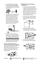
Antenna connectors
SMA-male on the Inside Antenna / F-male on the Outside Antenna
Antenna impedance 50 Ohms
Dimensions 4.5 x 6.44 x 1.19 in. or 11.43 x 16.35 x 3.02 cm
Weight 0.4 lbs or 0.18 kg
Frequency Frequency 704-746 MHz, 746-787 MHz, 824-894 MHz, 1850-1995 MHz, 1710-1755/2110-2155 MHz
Power output for a single phone (uplink) dBm Maximum Power
700 MHz
Band 17
700 MHz
Band 13
800 MHz 1900 MHz 1700 MHz
23.7 23.6 24.6 23.3 24.9
Power output for a single received channel (downlink) dBm Maximum Power
700 MHz
Band 17
700 MHz
Band 13
800 MHz 1900 MHz 2100 MHz
0.9 -1.0 2.1 6.1 5.8
Noise Figure (typical downlink/uplink) 7 dB nominal
Power Requirements 110-240 V AC, 50-60 Hz, 8 W
Each Signal Booster is individually tested and factory set to ensure FCC compliance. The Signal Booster cannot be adjusted
without factory reprogramming or disabling the hardware. The Signal Booster will amplify, but not alter incoming and outgoing
signals in order to increase coverage of authorized frequency bands only. If the Signal Booster is not in use for five minutes, it
will reduce gain until a signal is detected. If a detected signal is too high in a frequency band, or if the Signal Booster detects
an oscillation, the Signal Booster will automatically turn the power off on that band. For a detected oscillation the Signal
Booster will automatically resume normal operation after a minimum of 1 minute. After 5 (five) such automatic restarts, any
problematic bands are permanently shut off until the Signal Booster has been manually restarted by momentarily removing
power from the Signal Booster. Noise power, gain, and linearity are maintained by the Signal Booster’s microprocessor.