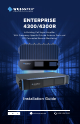
A Wilson Electronics Brand ENTERPRISE 4300/4300R In-Building Cell Signal Amplifier With Frequency-Specific Outside Antenna Ports and LTE Connected Remote Monitoring Installation Guide wilsonpro.com 866.294.
Index Package Contents 1 About The Enterprise 4300 & 4300R 2 Key Features 4 Post Install Setup 5 Menu System 6 Safety Guidelines 16 Specifications 18 Warranty 19
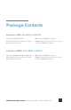
Package Contents Enterprise 4300 SKU 460152 & 460152F Enterprise 4300 Amplifier Wide Band Directional Antenna (qty. 1) Dome Antenna (qty. 4) 100 ft. Wilson400 Cable (qty. 5) 50 Ohm Lightning Surge Protector (qty. 1) 2 ft. Wilson400 Cable (qty. 1) Enterprise 4300R SKU 460153 & 460153F Enterprise 4300R Rack Mount Amplifier Wide Band Directional Antenna (qty. 1) Dome Antenna (qty. 4) 100 ft. Wilson400 Cable (qty. 5) 50 Ohm Lightning Surge Protector (qty. 1) 2 ft. Wilson400 Cable (qty.
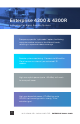
Enterprise 4300 & 4300R In-Building Cell Signal Amplifier Systems Frequency-specific “split mode” option, facilitating separate outdoor antennas for different bands, resulting in improved indoor coverage. Remote system monitoring. Connects to WilsonPro Cloud service via internal, pre-activated LTE modem. High max uplink power (up to +26 dBm): will reach far-away cell tower. High max downlink power (+17 dBm) for up to 100,000 sq ft coverage with a strong “5 bar” outside signal.
The Enterprise 4300 & 4300R cell signal amplifier systems provide significantly enhanced 4G LTE and 3G voice and data coverage inside buildings where cell signals may not otherwise penetrate. Installation of a Enterprise 4300 & 4300R cell signal amplifier system results in fewer dropped calls, improved voice quality, uninterrupted texts, and faster data speeds—along with better audio and video streaming.
Key Features Extended Dynamic Range (XDR) for continuous connectivity: XDR lets the Enterprise 4300 & 4300R systems work with an incoming signal and never shuts down due to a strong outside signal. Simple Wall-Mount & Rack Mount Installation: An indoor and outdoor port(s) are located on top of the amplifier for easy antenna connections, while an exposed mounting flange on each amplifier provides for simple installation.
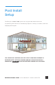
Post Install Setup The Enterprise 4300 & 4300R systems are designed with advanced internal programming, which allows it to automatically adjust for a variety of conditions, while still amplifying weak signals. THE SERVER PORT ANTENNAS WILL BE USED TO PROVIDE COVERAGE TO DIFFERENT AREAS WITHIN A BUILDING AND WILL BE INSTALLED WITH A MINIMUM OF 10 METERS SEPARATION BETWEEN SERVER PORT ANTENNAS.
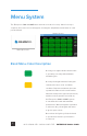
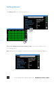
Menu System The Enterprise 4300 & 4300R takes about 8 seconds to boot up. Once boot up is complete, the home screen will appear, showing the amplification and status of each port and band. Home Screen Start Up Screen Band Menu Color Description A solid green light indicates that a band is operating correctly with maximum allowable gain. A solid yellow light indicates band gain reduction because of an oscillation condition.
(MENU SYSTEM cont.) A red light indicates a band has been shut down because of a severe oscillation condition or repeated oscillation. Reposition antennas (increase separation between indoor and outdoor antennas, and point in opposite directions) and then reboot (turn the unit off & on) the Enterprise 4300 & 4300R system to reactivate the band and maximize performance. When adequate separation is achieved, the red light(s) will return to green upon reboot. Gray indicates band has been disabled.
Settings Screen Tap ‘Settings Icon’ to view the Settings Screen. There are 5 Settings Screens represented by “tabs”. Tap the tab heading to view each Settings Screen. Note: Bands and Ports are disabled or enabled from the Cloud or Local Configuration Utility only.
(MENU SYSTEM - SETTINGS SCREEN cont.
(MENU SYSTEM - SETTINGS SCREEN cont.) Cloud Communication Settings Tab Note: The Reset Local Comm button (button name will likely change) is used in case the user has configured the amplifier such that the Local Configuration Utility is not accessible, e.g., if the communication preferences are set to “LTE Only”. The “reset” function will change the communication preferences to “LTE Preferred w/Ethernet Backup”.
(MENU SYSTEM - SETTINGS SCREEN cont.) Split Mode Configuration Split Mode is configured from the Local Configuration Utility and should be sent when using separate Donor/Outside Antennas for Band 4/25, Band 5, and Band 12/13. To go back to the Home Screen top on the Home Icon (in the lower right corner).
Band Status Screens To view specific band information (such as the strength of the received uplink & downlink signal, outside signal strength, and amplifier gain status) tap the desired band on the home screen.
(MENU SYSTEM - SETTINGS SCREEN cont.
Connectivity Status Screens Ethernet Status Icon The three icons in the upper right provide status related to the Ethernet connection, Cloud connection, and USB device (if inserted).
(MENU SYSTEM - CONNECTIVITY STATUS SCREENS cont.
Safety Guidelines Warnings o uphold compliance with network protection standards, all active cellular devices must maintain at T least 6 feet of separation distance from Panel and Dome antennas. Use only the power supply provided in this package. Use of a non-Wilson Electronics product may damage your equipment. The Signal Amplifier unit is designed for use in an indoor, temperature-controlled environment (operating temperature ranges from -40°C to 60°C – -40°F to 140°F).
Antenna Kit Options The following accessories are certified by the FCC to be used with the ENTERPRISE 4300/4300R. 314411 Wide Band Directional Antenna (Outside Antenna) 859902 50 Ohm Lightning Surge Protector 952300 100 ft. Wilson400 Cable (for Outside Antenna) 952302 2 ft. Wilson400 Cable 304412 Dome Antenna (Inside antennas) 952300 100 ft.
Specifications Model Number 460152 / 460152F / 460153 / 460153F FCC ID PWO460052 / PWO460052 / PWO460053 / PWO460053 IC ID 4726A-460052 / 4726A-460052 / 4726A-460053 / 4726A-460053 Connectors N-Connectors Antenna Impedance 50 Ohms Frequency 698-716 MHz, 729-756 MHz, 777-787 MHz, 824-894 MHz, 1850-1995 MHz, 1710-1755/2110-2155 MHz Power output for single cell phone (Uplink) dBm 700MHz Band12/17 700MHz Band13 800MHz 1700MHz 22.9 23.1 24.6 22.8 25.
Warranty 30 DAY MONEY-BACK GUARANTEE All WilsonPro products are protected by WilsonPro 30-day money-back guarantee. If for any reason the performance of any product is not acceptable, simply return the product directly to the reseller with a dated proof of purchase. 3 YEAR WARRANTY WilsonPro Amplifiers are warranted for three (3) years against defects in workmanship and/or materials. Warranty cases may be resolved by returning the product directly to the reseller with a dated proof of purchase.
Notes NEED HELP? 20 support.wilsonpro.com IN-BUILDING CELL SIGNAL AMPLIFIER 866.294.
Notes NEED HELP? support.wilsonpro.com 866.294.
A Wilson Electronics Brand 3301 East Deseret Drive, St. George, UT www.wilsonpro.com | support.wilsonpro.com Copyright © 2019 2016 Wilson Electronics. All rights reserved. Wilson Electronics products covered by U.S. patent(s) and pending application(s) For patents go to: weboost.