Installation Guide A WILSON ELECTRONICS BRAND Home Studio / Home Studio Lite Cell Signal Booster
Index Package Contents. . . . . . . . . . . . . . . . . . . . . . . . . . . . . . . . . . . . . . . . . . . . . . . . . . . . . . . . . . . . 1 STEP 1 Attach Inside Antenna to Booster & Place in Desired Location . . . . . . . . . . . . . . . 2 STEP 2 Mount & Point Outside antenna Toward Nearest Cell Tower. . . . . . . . . . . . . . . . . 2 STEP 3 Route & Connect Outside Antenna To Booster . . . . . . . . . . .
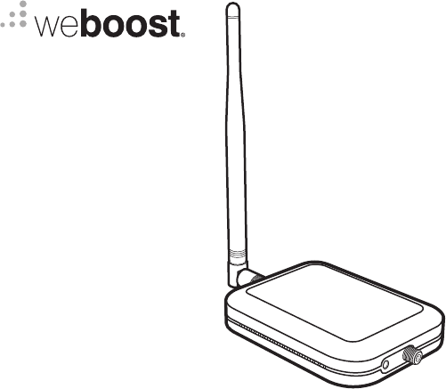
Package Contents Home Studio/Home Studio Lite Booster & Inside Antenna 2–30 ft.
STEP 1 Attach Inside Antenna to Booster & Place In Desired Location Inside Antenna Attach the Inside Antenna to Home Studio/Home Studio Lite booster and place in room where stronger cell signal is needed. STEP 2 Mount & Point Outside Antenna Toward Nearest Cell Tower Pole mounting is preferred because it will be easier to adjust to the direction of the cell tower. Use the U-Bolts to attach the Antenna to a pole or exhaust pipe on roof.
(STEP 2 cont.) Point the Outside Antenna toward the nearest cell phone tower. To find the nearest tower, use an app such as ‘Open Signal’. This is the most critical step of the installation process because it will determine the overall performance of the booster system. Side Mounting Side mounting is a option if you can still obtain strong signal. Note: Drip holes should be pointed down towards ground.
STEP 3 Route & Connect Outside Antenna To Booster Connect the white RG-6 Cable to Outside Antenna and route and connect cable to Home Studio/Home Studio Lite booster. All connections should be finger tightened only. STEP 4 Power Up The Booster & Optimize The System Plug the Power Supply into wall outlet then connect into end of booster. NOTE: We strongly recommend using a power strip with surge protection.
(STEP 4 cont.) After powering up your system, check to see how your talk, text, and data rates have improved. If more is desired, you can optimize your system. Rotate the Outside Antenna in 1/8 turn increments, after each turn, unplug and reconnect the booster to power while observing the signal level on your cell phone from the Inside Antenna’s projected area. When you have determined a direction that gives you the strongest signal, secure the Outside Antenna in place.
Status Light Patterns Ban d 13 Ban d 12 GREEN This indicates that your Home Studio or Home Studio Lite is functioning properly and there are no issues with installation. SOLID RED Band has shutoff. This is due to a feedback loop condition called oscillation. This is a built in safety feature that causes a band to shut off to prevent harmful interference with a nearby cell tower. Refer to Troubleshooting section.
(Status Light Patterns cont.) already experiencing the desired signal boost, then no further adjustments are necessary. If you are not experiencing the desired boost in coverage then refer to the Troubleshooting section. BLINKING GREEN, YELLOW This indicates Band has reduced gain. This indicates that one or more of the booster bands has reduced power due to overload from nearby cell tower. This is a built in safety feature to prevent harmful interference with a nearby cell tower.
Troubleshooting FIXING RED LIGHT ISSUES This involves Solid Red & Blinking Green/Red lights. ■ Tighten all cable connections (be sure to handtighten only, do NOT use tools). You may want to undo and redo the connection completely. Unplug and re-plug in power supply. ■ Increase the distance (horizontally or vertically) between the Outside and Inside antenna. Add included cable if needed. Un-plug and re-plug in power supply.
Safety Guidelines Verify that both the Outside Antenna and the adapter extension cable are connected to the Signal Amplifier before powering up the Signal Amplifier. se only the power supply provided in this package. Use of an incorrect power supply may damage your U equipment. RF Safety Warning: Any antenna used with this device must be located at least 8 inches from all persons. AWS Warning: The Outside Antenna must be installed no higher than 10 meters (31’9”) above ground.
(Safety Guidelines cont .) FOR MORE INFORMATION ON REGISTERING YOUR SIGNAL BOOSTER WITH YOUR WIRELESS PROVIDER, PLEASE SEE BELOW: T-Mobile/Sprint/MetroPCS: https://support .t-mobile .com/docs/DOC-9827 Verizon Wireless: http://www .verizonwireless .com/wcms/consumer/register-signal-booster .html AT&T: https://securec45 .securewebsession .com/attsignalbooster .com/ U.S. Cellular: http://www .uscellular .com/uscellular/support/fcc-booster-registration .
. HOME STUDIO BAND 2 Outside antenna maximum permissible antenna gain (dBi) 50Ω BAND 4 6.1 HOME STUDIO LITE 5.8 BAND 12 Outside antenna maximum permissible antenna gain (dBi) 50Ω 4.9 BAND 5 4.5 BAND 12 4.9 BAND 13 4.9 BAND 13 4.
Specifications Home Studio Cell Signal Booster 460066 Model PWO460066 FCC F-Female / SMA Female Connectors 50 Ohms / 75 Ohms Antenna Impedence Frequency Power output for single cell phone (Uplink) dBm Power output for single cell phone (Downlink) dBm Noise Figure Isolation Power Requirements 698-716 MHz, 728-756 MHz, 777-787 MHz, 824-894 MHz, 1850-1995 MHz, 1710-1755/2110-2155 MHz 700 MHz B12/17 23.3 9.4 700 MHz B13 22.2 9.6 800 MHz B5 23.3 1700 MHz B4 22.1 7.0 11.8 1900 MHz B2 21.8 13.
Specifications Home Studio Lite Cell Signal Booster 460065 Model PWO460065 FCC F-Female / SMA Female Connectors 50 Ohms / 75 Ohms Antenna Impedence Frequency Power output for single cell phone (Uplink) dBm Power output for single cell phone (Downlink) dBm Noise Figure Isolation Power Requirements 698-716 MHz, 728-756 MHz, 777-787 MHz 700 MHz B12/17 24.3 700 MHz B13 23.0 11.7 12.9 5.0 dB nominal > 90 dB 5V 4A Each Signal Booster is individually tested and factory set to ensure FCC compliance.
Notes 14
Notes 15
Notes 16
2 YEAR WARRANTY weBoost Signal Boosters are warranted for two (2) years against defects in workmanship and/or materials. Warranty cases may be resolved by returning the product directly to the reseller with a dated proof of purchase. Signal Boosters may also be returned directly to the manufacturer at the consumer’s expense, with a dated proof of purchase and a Returned Material Authorization (RMA) number supplied by weBoost. weBoost shall, at its option, either repair or replace the product.
A WILSON ELECTRONICS BRAND 3301 East Deseret Drive, St. George, UT 866.294.1660 www.weboost.com support.weboost.com Copyright © 2020 weBoost. All rights reserved. weBoost products covered by U.S. patent(s) and pending application(s) For patents go to: weboost.com/us/patents NOT AFFILIATED WITH WILSON ANTENNA GDE000280_PROOF2_09.14.