Signal Booster Installation Guide DB Pro™ Adjustable Gain 800/1900 MHz In-Building Wireless Smart Technology ™ Signal Booster DB Pro™ Contents: How it Works . . . . . . . . . . . . . . . . . . . . . . . . . . . . . . . . . 1 Quick Install Overview . . . . . . . . . . . . . . . . . . . . . . . . . . 2 Installation Diagram . . . . . . . . . . . . . . . . . . . . . . . . . . . . 3 Selecting a Direction for the Outside Antenna . . . . . . . . 5 Finding the Strongest Signal . . . . . . . . . . . . . . . . .
Installation Instructions for the Following Wilson Electronics Signal Booster: DB Pro™ Adjustable Gain In-Building Wireless 800/1900 MHz Smart Technology ™ Signal Booster Model # 271265 FCC ID: PWO271265 IC: 4726A-271265 The term “IC” before the radio certification number only signifies that Industry Canada technical specifications were met.
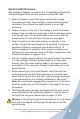
Quick Install Overview See Installation Diagram on pages 3 & 4. Contact Wilson Electronics Technical Support Team with any questions at 866-294-1660. 1. Select a location to install the signal booster that is away from excessive heat, direct sunlight, moisture and has proper ventilation. Do not place the signal booster in an air-tight enclosure. 2. Select a location on the roof of the building to install the outside antenna. Use a cell phone in test mode to find the strongest signal from the cell tower.
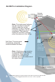
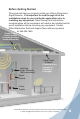
AG DB Pro Installation Diagram Outside Antenna (Wide Band Antenna option shown) Note: The inside panel antenna may be mounted on the wall directly under the outside antenna if 15 feet of vertical/ horizontal separation can be maintained. The preferred method for the best coverage, place the antenna in the ceiling. Null Zone: The area under the antenna, where the antenna radiates the least. Note: A lightning surge protector is recommended for all building installations.
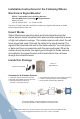
Before Getting Started This guide will help you properly install your Wilson Electronics Signal Booster. It is important to read through all of the installation steps for your particular application prior to installing any equipment. Read through the instructions, visualize where all the equipment will need to be installed and do a soft installation before mounting any equipment. Contact Wilson Electronics Technical Support Team with any questions at: 866-294-1660.
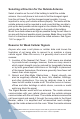
Selecting a Direction for the Outside Antenna Select a location on the roof of the building to install the outside antenna. Use a cell phone in test mode to find the strongest signal from the cell tower. To get the strongest signal possible, it is very important to set up your outside antenna properly.
picks up a signal from your cellular device, the signal booster amplifies that signal and transmits it through the cable to the outside antenna and back to the cell tower. (Note: The Signal Booster will only operate if there is an adequate signal to amplify.) Finding the Strongest Signal Cell Signal Outside Wide Band Antenna Cell Tower When installing your signal booster’s outside antenna, aiming it towards the best signal source from your service provider is important.
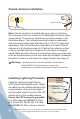
Outside Antenna Installation Wide Band Antenna option shown Drip hole on bottom Cell Cell Tower Tower Note: Use the directions included with your choice of antenna, the instructions here are meant for the Wide Band Antenna option shown above. The antenna should be mounted as shown in the illustration above. The included mounting bracket is adjustable and will accommodate pipe diameters from 1.25” to 2” (pipe sold separately).
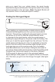
Mounting Tips for Running Outside Antenna Cable If you are mounting the outside antenna on the roof of your building, we have found that it is easiest to run your cable underneath the down side of your roof’s flashing. If you have satellite TV service installed at your home or office, you may be able to follow the same route as the satellite TV cables that are already running from the outside of your building to the inside.
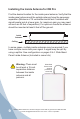
Installing the Inside Antenna for DB Pro Find the desired location for the inside panel antenna. Verify that the inside panel antenna and the outside antenna have the necessary separation (Minimum of 15 vertical/horizontal feet if installed with signal booster set at a lower gain, for maximum gain you may need as much as 50 feet of separation). For optimum results the antenna should be mounted at least 6 feet off the ground.
Installing a Wilson Electronics Signal Booster Select a location to install the signal booster that is away from excessive heat, direct sunlight, moisture and that has proper ventilation. Do not place the signal booster in an air-tight enclosure. Recommended installation locations for in-building signal boosters are: • On a shelf • In a closet • Near a power outlet. Note: It is important to have adequate air ventilation. Maintain at least 6 inches of clearance from surrounding objects.
Powering up a Wilson Electronics Signal Booster 1. Never point the front of a directional outside antenna toward the inside antenna. See Figure 2 on page 12. 2. Ensure that both the outside antenna coax cable and the inside antenna coax cable are connected to the signal booster and the connections are tight before powering up the signal booster. 3. Plug the 6-volt power supply into the signal booster input marked “POWER” (carefully, to avoid damaging the center pin) and then into a wall outlet. 4.
Figure 1 CORRECT INSTALLATION Point antennas away from each other Outdoor Antenna Inside Panel Antenna Signal Booster Figure 2 INCORRECT INSTALLATION Never point antennas toward each other Outdoor Antenna Inside Panel Antenna Signal Booster Contact Wilson Electronics Technical Support Team with any questions at 866-294-1660 or email: tech@wilsonelectronics.com. Hours: 7 am to 6 pm MST.
Understanding the Signal Booster Lights and Troubleshooting During installation mode the signal booster is resetting itself very quickly to aid the installer. The Signal Booster is equipped with two indicator lights, one for the 800 MHz band and the other for the 1900 MHz band. For the first 15 minutes that the booster is plugged in, it is programed for a test and alignment period.
adequate for good coverage, you will need to turn the gain to maximum and then turn the outside antenna away from the cell tower until the light turns to blinking green. If the booster will not respond, turn the gain down 5 dB and move the outside antenna. Continue to adjust the gain and the antenna position until the light turns blinking green. Contact Wilson Electronics Technical Support Team for assistance: 866-294-1660. 3.
Warnings Warning: The directional antenna must always be located so the back or side points to the inside antenna. Never point the front of the outside antenna toward the inside antenna – this is to prevent oscillation. Warning: Connecting the signal booster directly to the cell phone with use of an adapter will damage the cell phone. Warning: Use only the power supply provided in this package. Use of a non-Wilson Electronics product may damage your equipment.
About Wilson Electronics Wilson Electronics, Inc. has been a leader in the wireless communications industry for over 40 years. The company designs and manufactures signal boosters, antennas and related components that significantly improve cellular telephone signal reception and transmission in a wide variety of applications, both mobile and in-building.
30-Day Money-Back Guarantee All Wilson Electronics products are protected by Wilson Electronics 30-day money-back guarantee. If for any reason the performance of any product is not acceptable, simply return the product directly to the reseller with a dated proof of purchase. 1-Year Warranty Wilson Electronics Signal Boosters are warranted for one (1) year against defects in workmanship and/or materials.
Disclaimer: The information provided by Wilson Electronics, Inc. is believed to be complete and accurate. However, no responsibility is assumed by Wilson Electronics, Inc. for any business or personal losses arising from its use, or for any infringements of patents or other rights of third parties that may result from its use. Copyright © 2011 Wilson Electronics, Inc. All rights reserved.
Signal Booster Specifications IC: 4726A-271265 FCC ID: PWO271265 DB Pro Specifications Model Number 271265 Antenna connectors F-Female Antenna impedance 75 ohms 6.5 x 4.5 x 1.75 inch (16.5 x 11.4 x 4.4 cm) Dimensions Weight 0.47 lbs (0.213 kg) Frequency 1 824-894 MHz / 1850-1990 MHz Passband Gain (nominal) 800 MHz * 1900 MHz 2 20 dB Bandwidth (nominal) Downlink 800 MHz 45 MHz 1900 MHz 88 MHz Power Output 4 800 MHz 1900 MHz Power output for single cell phone (uplink) 30.8 dBm 30.