This Manual is Bookmarked Operating Instructions — Parts Manual 7 x 12 Cut-off Band Saw Models: 3400/3410 WHM TOOL GROUP, Inc. 2420 Vantage Drive Elgin, Illinois 60124 Ph.: 800-274-6848 www.wmhtoolgroup.com 177339 Part No.
Warranty and Service WMH Tool Group, Inc., warrants every product it sells. If one of our tools needs service or repair, one of our Authorized Service Centers located throughout the United States can give you quick service. In most cases, any of these WMH Tool Group Authorized Service Centers can authorize warranty repair, assist you in obtaining parts, or perform routine maintenance and major repair on your WILTON® tools. For the name of an Authorized Service Center in your area call 1-800-274-6848.
Table of Contents Cover Page .......................................................................................................................... 1 Warranty ................................................................................................................................ 2 Table of Contents .................................................................................................................. 3 General Specifications ............................................................
General Specifications The Wilton Models 3400 and 3410 cut-off band saws are designed for high production cut-off work. Four cutting speeds and a hydraulic feed control allows the efficient cutting of virtually any material. A removable table also allows the saw to function as a vertical band saw. The Model 3410 is equipped with an optional coolant system which can greatly extend blade life and speed the cutting of a variety of materials which are best cut with cutting fluids and coolants.
- Misuse of this machine can cause serious injury. - For safety, machine must be set up, used and serviced properly. - Read, understand and follow instructions in the operator’s and parts manual which was shipped with your machine. When setting up machine: - Always avoid using machine in damp or poorly lighted work areas. - Always be sure machine is securely anchored to the floor. - Always keep machine guards in place. - Always put start switch in OFF“ position before plugging in machine.
20.Some dust created by power sanding, sawing, grinding, drilling and other construction activities contains chemicals known to cause cancer, birth defects or other reproductive harm. Some examples of these chemicals are: Lead from lead based paint crystalline silica from bricks and cement and other masonry products, and arsenic and chromium from chemically-treated lumber. 21.Your risk from those exposures varies, depending on how often you do this type of work.
Operating Instructions Using the vise The vise on the saw table has two jaws. The jaw closest to the right hand side of the table is the stationary jaw. This jaw is firmly secured to the table using its pivot and lock bolts. When making a straight cut the stationary jaw is at right angles to the saw blade. When making an angle cut, the stationary jaw is first loosened, then adjusted to the desired angle, then secured to the table, again.
eventually catch the thrust shaft and allow you to open or close the locking jaw at its new lead screw position. When you slide the jaw to a new position, you can see where the nearest lead screw groove is by looking through the slot above the lead screw. (See Figure 1.) Changing the locking jaw location: 1. Lift the quick release handle. 2. Slide the jaw until it contacts the workpiece. 3. Turn the lead screw handle until the thrust shaft drops into a groove. 4.
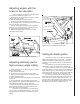
Adjusting angles with the scale on the saw table There is a scale on the rear of the saw base which can be used to establish the angle of cut. 1. Raise the saw arm to full height and lock it in position with the quick shut-off valve. 2. Slide the locking jaw to full open position. 3. Loosen the pivot and lock bolts shown in Figure 1. 4. Lay a straight edge on the saw frame so it contacts the stationary vise jaw. (See Figure 3.) 5.
Controlling the cut: Hydraulic feed control 10 The weight of the saw arm typically provides all of the force needed to move the saw blade through the workpiece. In fact, if the full weight of the arm is allowed to make the cut, rapid blade wear and poor cutting accuracy will result. Therefore, a hydraulic feed control is provided which gives the operator control over the speed and efficiency of cutting.
Changing blade speeds The Models 3410 and 3400 are 4-speed cut-off saws. The different speeds are obtained by changing the position of the drive V-belt which connects the motor pulley to the drivewheel gearbox pulley. To change blade speeds: 1. Disconnect the saw from its electrical power source to prevent any possibility of accidental motor start-up. 2. Allow the saw arm to rest at its full horizontal position. 3. Open the pulley cover to expose the V-belt and pulleys. 4.
Right angle cuts -single pieces of stock 1. Raise the saw arm to its full up, open position. 2. Pull up on the quick release handle on the locking vise jaw and slide the vise jaws apart. 3. Place the stock on the saw table, between the vise jaws. If the stock is long, support the stock with appropriate infeed and outfeed supports. 4. Pull up on the quick release handle and slide the locking vise jaw up against the workpiece. 5.
Figure 8: Placing workpieces in the vise 13
Maintenance Replacing blades 1. Disconnect the saw from its electrical power source to prevent accidental start-ups. 2. Raise the saw arm to its full vertical position and lock it in place using the quick shut off valve on the hydraulic control cylinder. 3. Lift the safety cover in the lower portion of the blade guard door by sliding it upward. There is no need to remove it completely from its slot. 4.
Blade alignment adjustments The blade can suffer from several out-of-adjustment conditions. These conditions are shown in Figure 10. Figure 10: Blade alignment fault conditions Establishing a reference surface for blade adjustment So long as major changes and adjustments to the blade guide system are not made, you will not have to perform the following procedure.
Replacing blade guide and support components All component parts are secured with nuts, bolts, washers, or snap rings. To remove and replace any component, first remove the blade according to instructions in Replacing blades. Then remove and replace the faulty component(s). The guide and support bearings are mounted on eccentric shafts to permit adjustment of the bearing axis. See Figure 11.
Adjusting blade vertical: The blade guide bearing seat can rotate as needed to make the blade vertical to the saw table. Follow these instructions. 1. With the saw arm in horizontal position, put a machinists square on the table, and against the blade, as shown. The blade should be square (vertical) to the table. If not... 2. Slightly loosen the socket head cap screw which secures the bearing seat to the bracket bar. 3. Use a wrench to rotate the seat until the blade is vertical. (See Figure 13.) 4.
Adjusting guide bearings Replacing guide bearings There are eight side blade guide/support bearings. These bearings are installed in the bearing seat, and the seat is attached to the sliding adjustment bracket. These bearings are stacked, with two bearings on each adjustment eccentric. The width of each pair of stacked bearings is slightly less than the width of a blade. The force against each of the bearings in each stack is not equal. This is because the bearings are twisting the blade.
Replacing the drive wheel 1. Complete steps 1 through 6 in Replacing blades. 2. Remove the snap ring which secures the lower wheel to the gearbox output shaft. 3. Pull the wheel off of the gearbox output shaft using a suitable puller. 4. Inspection: Examine the wheel for damage on its drive edge, shoulder, or the shaft boss. Replace if any faults are found. 5. Reinstall the wheel by pressing and/or tapping it back onto the shaft using a soft-faced mallet. 6.
Servicing the hydraulic control cylinder 20 Over a long period of service the hydraulic control cylinder may need replacement of its internal seals. Use the following procedure. (See Figure 18.) 1. Lower the arm to its horizontal position. 2. Remove the upper fasteners, lower set screw, and pin which secure the cylinder to the saw arm and saw base. 3. Working over a container suitable to hold the fluid, pull the control rod to its full extended position. 4.
Machine Set-up The saw delivered to you has been adjusted at the factory. A number of test pieces have been cut using the saw to verify the accuracy of cutting. Therefore, the only set-up operations required before releasing the saw for service are spotting the saw and establishing the electrical connections to the motor. If ordered with the coolant kit, the kit is typically installed at the Wilton factory.
Installing the coolant kit 1. Install the baffle in the tank so the pump is held at one end of the tank. 2. Put the tank and pump assembly in the flanges which hold it in the saw base. The pump should be at the saw motor end of the base. 3. Install the nozzle assembly in the fixture in the righthand guide bearing bracket and secure it with the set screw in the fixture. 4. Install the delivery hose between the nipple on the pump and the nipple on the nozzle assembly. 5.
Troubleshooting Problem Excessive blade breakage Probable cause Material loose in the vise Incorrect feed or speed Incorrect blade tension Teeth in contact with work before saw is started Blade rubs on wheel flange Misaligned blade guides Blade too thick for wheel diameter Premature blade dulling Cracking at weld Teeth too coarse Too much blade speed Inadequate feed pressure Hard spot or scale on material Work hardening of material (especially stainless steel) Blade installed backwards Incorrect coo
Troubleshooting Feed pressure too great Guide bearings not adjusted properly Inadequate blade tension Blade guides incorrectly spaced Dull blade Incorrect speed Rough cuts Blade guide assembly loose Blade guide bearing assembly loose Blade tracking too far away from wheel flanges Worn upper wheel bearings Loose upper wheel mounting assembly Too much feed or speed Blade too coarse Incorrect blade for material Blade twisting Cut is binding blade Too much blade tension Loose guide bearing eccentrics Worn
Replacement Parts This section provides exploded view illustrations that show the replacement parts for the Model 3400 and 3410 7-Inch x 12-Inch Horizontal Cut-Off Band Saw. Also provided are parts listings that provide part number and description. The item numbers shown on the illustration relate to the item number in the facing parts listing. Order replacement parts from: WHM TOOL GROUP, Inc. 2420 Vantage Drive Elgin, Illinois 60124 Ph.
Exploded View - Saw Head 26
Parts List - Saw Head Ref. no. 1 2 4-1 5 6 7 8 9A 10A 11A 12 12 13 14 Part.no. 5710011 5710021 5710041 5710051 5710061 5710071 5710081 5710091 5710111 5710121 5710131 5711921 5710141 Description Pulley cover Motor pulley HH screw 5/16X1 Motor 3/4 HP 115V 1PH Motor mount plate assy. HH screw 5/16x5/8 HH screw 5/16x1-1/4 Tapping screw 6mmx20 Gearbox cover Gearbox gasket Trnsmsion gear 20mm bore Trnsmsion gear 25mm bore Ball bearing 6005 Saw Blade: 5632141 3/4 X .032 X 93" 8 TPI 5632151 3/4 X .
Exploded View - Saw Base 28
Parts List - Saw Base Ref. Part no. Description no.
Parts List - Hydraulic Cylinder 30 Ref. Part no. Description no. 1 2 3 4 5 6 7 8 5517547 5517548 5517549 5517550 5517551 5517552 5517553 5517554 Dust cover Retaining ring Oil-seal Oil-piston O-ring Cylinder body Oil pressure regulator Oil duct Qty.