This Manual is Bookmarked Operating Instructions — Parts Manual Disc, Belt, and Combination Disc/Belt Sanders Models: 4200A, 4300A, 4400A 4200A Disc/Belt Sander WHM TOOL GROUP 2420 Vantage Drive Elgin, Illinois 60123 Ph.: 800-274-6848 www.wmhtoolgroup.com 4300A 6 Inch Belt Sander 4400A 12 Inch Disc Sander Part No.
This manual has been prepared for the owner and operators of a Wilton Sander. Its purpose, aside from machine operation, is to promote safety using accepted operating and maintenance procedures. To obtain maximum life and efficiency from your Sander and to aid in using it safely, please read this manual thoroughly and follow instructions carefully. Warranty and Service WMH Tool Group warrants every product it sells.
Table of Contents Cover Page ......................................................................................................................................... 1 Warranty .............................................................................................................................................. 2 Table of Contents ................................................................................................................................ 3 Machine and Manual Overview ............
Machine and Manual Overview Wilton Abrasive Finishing Machines are available in three different configurations: disc, belt, and combination disc and belt. Each configuration is a rugged, heavy-duty machine designed for maximum high production work in an industrial environment. The speed of stock removal and the quality of finish achieved is determined largely by the aggressiveness of the abrasive disc or belt mounted on the machine.
General Specifications Disc Sander Belt Sander Disc/Belt Sander Table size 12x16 3/8 in. (254x416mm) 7 3/8x14 3/4 in. (187x355mm) Disc:12x16 3/8 in. (254x416mm) Belt: 7 3/8x14 3/4 in. (187x355mm) Table tilt 45° down, 20° up 45° down, 20° up (both) 45° down, 20° up Miter gauge groove 3/8x3/4 in. (9.5x19mm) 3/8x3/4 in. (9.5x19mm) (both) 3/8x3/4 in. (9.
General Machinery Cautions - Misuse of this machine can cause serious injury. - For safety, the machine must be set up, used and serviced properly. - Read, understand and follow the instructions in the operator’s and parts manual which was shipped with your machine. When setting up the machine: - Always avoid using the machine in damp or poorly lighted work areas. - Always be sure the machine is securely anchored to the floor. - Always keep the machine guards in place.
General Electrical Cautions Wire Sizes This machine should be grounded in accordance with the National Electrical Code and local codes and ordinances. The work should be done by a qualified electrician. The machine should be grounded to protect the user from electrical shock. Caution: For circuits that are a great distance from the electrical service box, the wire size must be increased in order to deliver ample voltage to the motor.
Operating Instructions These sanders can be used to remove stock from a wide variety of machinable materials. Different materials require different grit types and grades to achieve the desired stock removal rate and surface finish. Please consult with your abrasive materials supplier for specific recommendations on the correct grit material and grade required for your specific needs. When removing stock from soft materials (wood, plastic, etc.) these machines are typically called "sanders.
Adjusting the Disc Sander Table 1. Unlock the two locking knobs underneath the table at each end. (See Figure 4.) 2. Using the pointer and scale, set the angle to any required angle between 20o upward and 45o downward. 3. Lock the two locking knobs underneath the table. CAUTION: NEVER ADJUST THE TABLE ANGLE WHILE THE SANDER IS RUNNING. ALWAYS TURN THE MOTOR OFF BEFORE ADJUSTING THE TABLE ANGLE.
Maintenance Belt Replacement 10 1. Disconnect the power to the machine to prevent accidental start-ups. If the machine is plugged into an outlet, unplug it. If the machine is hardwired to a branch circuit with a junction box, remove the fuse or trip the circuit breaker to the branch. 2. Remove the lock knob and top cover (See Figure 6). 3. Remove the side guard and table. 4. Release the belt tension by turning the tension handle in a counterclockwise direction (See Figure 7).
Track Mechanism Maintenance Replacing the V-Belt. While the use of a dust collection system can extend service intervals, an accumulation of dust will almost certainly require periodic cleaning of the tracking mechanism. The more continuous the use of the machine, the more frequently this maintenance should be performed. As mentioned in the preceding section, the need for required maintenance is often indicated by difficulty in adjusting the tension/tracking mechanism. 1.
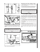
Figure 13: Removing the guard and drive disc, together. Figure 11: Rotating the machine casting to remove the disc guard bolts 6. Remove the two bolts, underneath the machine casting, that secure the disc guard to the casting (See Figure 11). 12 Figure 12: Locating the set screws that secure the disc to the arbor 5. Through the hole in the disc guard casting, locate and remove the TWO set screws that secure the drive disc to the arbor.
Machine Setup Basic Setup Figure 14: Loosening pulley set screws to allow the adjustment of pulley on arbor shaft. 1. Position the machine where it will be located on the shop floor. When positioning the machine, consider the type of work which will be done on it so you allow sufficient room not only for the workpieces, but also for service to the machine. 2. Open the door in the base of the machine and, using the holes in the base as a template, mark the floor for the position of the hold-down bolts. 3.
Disc Table Angle Adjustment 1. Disconnect the power to the machine to prevent accidental start-ups. 2. Loosen the table locking knobs on either end of the table. 3. Using a machinist's square against the table and disc, set the table at exactly 90o to the disc (See Figure 15). 4. Tighten the table locking knobs. 5. Check the pointer. If it is not exactly on the zero mark, loosen the pointer attaching screw, adjust the pointer, and retighten the screw. 6. Reconnect the power to the machine.
Belt Table Miter Slot Parallelism Adjustment 1. Disconnect the power to the machine to prevent accidental start-ups. 2. Set the table angle to zero. 3. Place a scale or adjustable machinist's square against either the left or right edge of the belt or platen and measure the distance to the miter slot edge (See Figure 19). 4. Move the measuring device to the opposite edge of the belt or platen and measure the distance to the miter slot. 5.
Adjusting or Replacing the Platen Electrical 1. Disconnect the electrical power to the machine to prevent accidental start-ups. 2. Remove the top cover, side guard and belt as outlined in Belt Replacement. 3. Remove the table by unscrewing the locking handling and lifting the complete table assembly, from the machine. 4. If you are replacing the platen, remove the three screws that hold it to its mount -- then install the new platen and replace the mounting screws finger tight. 5.
Single Phase Electrical Hookup Three Phase Electrical Hookup When connecting your machine to single phase power, you may be connecting to either 115 or 230 volts, depending upon the motor type provided. Local codes may, or may not, permit the use of a plug type of connection for your machine. Where a plug connection is permitted, the following installation practices must be followed: 1. The plug used must be a grounding type of plug.
Troubleshooting Fault Motor will not run Probable cause 1. Motor is defective 2. Voltage is too low 3. Switch is defective 4. Branch circuit fuse is blown or the circuit breaker is tripped 5. Branch is shut down for service 6. Open circuit in the wiring Motor stalls easily 1. Low voltage. 2. Fuse is blown (three phase motors only.) 3. Improper wiring. Abrasive belt or disc slows down although motor keeps running at working speed Poor tracking Suggested remedy 1. Replace the motor. 2.
Electrical Schematics JIC Packages Figures 25 and 26, below: Wiring diagrams for 230 and 460 VAC with controller with warning light. Figure 27 and 28, below: Wiring diagrams for 230 and 460 VAC with push button switch.
Electrical Schematics Standard 1 phase and 3 phase machines Figure 30: Schematic diagram for single phase motor. Figure 31: Schematic diagram for 3-phase motor. Figure 32: Motor connection diagram for 1-phase motor. Figure 33: Motor connection diagram for 3-phase motor. Replacement Parts 20 This section provides exploded view illustrations that show the replacement parts for the Model 4400A, 4300A, 4200A Disc, Belt, and Combination Disc/Belt Sanders.
Exploded View – Model 4200A Belt and Disc Sander Assembly 21
Parts Listing – Model 4200A Belt and Disc Sander Assembly 22 Ref # 1 2 3 4 5 6 7 8 9 10 11 12 13 14 15 16 17 18 19 20 21 22 23 24 25 26 27 28 29 30 31 32 33 34 35 36 37 38 39 40 41 42 43 44 45 46 47 48 49 50 51 52 53 54 55 Part No. Description Qty.
Exploded View – Model 4300A Belt Sander Assembly 23
Parts Listing – Model 4300A Belt Sander 24 Ref # 1 2 3 4 5 6 7 8 9 10 11 12 13 14 15 16 17 18 19 20 21 22 23 24 25 26 27 28 29 30 31 32 33 34 35 36 37 38 39 40 41 42 43 44 45 46 47 48 49 50 51 Part No.
Exploded View – Model 4400A Disc Sander Assembly 25
Parts Listing – Model 4400A Disc Sander Assembly 26 Ref # 1 2 3 4 5 6 7 8 9 10 11 12 13 14 15 16 17 18 19 20 21 22 23 24 25 26 27 28 29 30 31 32 33 34 35 36 37 38 39 40 41 42 43 44 45 46 Part No.
Exploded View - Base Assembly (All Models) Ref # 301 302 303 304 305 306 307 308 309 309 310 311 312 313 314 315 316 317 318 319 Part No. 5511743 TS-1540081 5511745 5511729 5052431 TS-1490031 TS-1550061 TS-1540061 5514650 5514651 TS-1550061 TS-1490011 TS-2361081 9133081 5514703 5511753 5511754 9139391 TS-2361081 TS-2360121 Description Enclosure Hex Nut, M12 Adjustable Mount Large Cover Motor Mounting Plate HHCS, M8 x 20 Flat Washer, M8 Hex Nut, M8 1.5 HP 115/230V 1 Ph. 1.5 HP 115/230V 1 Ph.
Dust Collection System (Optional) Installation Transport the shipping container to the installation site. Unpack the dust collection system and check for damage. Contact the carrier if damage is found. Open the installation kit (refer to Optional Accessories in the parts listing for installation kits). Install the cover and debris collection drawer if removed. Slip a hose clamp over the 3-inch vacuum hose. Slip the hose on the inlet duct. Move the clamp over the duct to secure the hose.
Disassembly Disassembly of the dust collection system is only required to replace the motor or the fan components. The motor switch, if failed, can be replaced without removal of the motor. 1. Remove the chip drawer (2) and cover (4) from the base (1). 2. Remove the filter cover (5) and filter (6). Replace the filter if required. 3. Remove five nuts (10) and lock washers (11) from the studs at the rear of the base (1). 4. Remove four nuts (12) and lock washers (13) from the screws (14).
Exploded View – Model 5511885 Dust Collection System 15 14 16 21 22 26 24 28 19 9 20 12 23 13 18 27 17 11 25 10 5 4 6 REAR VIEW 30 7 8 1 2 FRONT VIEW 3
Parts Listing – Model 5511885 Dust Collection System Ref. No.
WMH Tool Group 2420 Vantage Drive Elgin, Illinois 60123 Phone: 800-274-6848 www.wmhtoolgroup.