This Manual is Bookmarked Operating Instructions and Parts Manual 16-Inch Woodworking Band Saw Model JWBS-16B WMH TOOL GROUP, Inc. 2420 Vantage Drive Elgin, Illinois 60124 Ph.: 800-274-6848 www.wmhtoolgroup.com Part No. M-708749B Revision A 03/08 Copyright © 2008 WMH Tool Group, Inc.
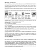
Warranty and Service WMH Tool Group, Inc., warrants every product it sells. If one of our tools needs service or repair, one of our Authorized Service Centers located throughout the United States can give you quick service. In most cases, any of these WMH Tool Group Authorized Service Centers can authorize warranty repair, assist you in obtaining parts, or perform routine maintenance and major repair on your JET® tools. For the name of an Authorized Service Center in your area call 1-800-274-6848.
Table of Contents Warranty and Service.................................................................................................................................... 2 Table of Contents.......................................................................................................................................... 3 Warning ......................................................................................................................................................... 4 Introduction ....
Warning 1. Read and understand the entire owner's manual before attempting assembly or operation. 2. Read and understand the warnings posted on the machine and in this manual. Failure to comply with all of these warnings may cause serious injury. 3. Replace the warning labels if they become obscured or removed. 4. This band saw is designed and intended for use by properly trained and experienced personnel only.
blahblahblah 20. Make your workshop child proof with padlocks, master switches or by removing starter keys. 21. Give your work undivided attention. Looking around, carrying on a conversation and “horse-play” are careless acts that can result in serious injury. 22. Maintain a balanced stance at all times so that you do not fall or lean against the blade or other moving parts. Do not overreach or use excessive force to perform any machine operation. 23. Use the right tool at the correct speed and feed rate.
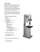
Introduction This manual is provided by Jet covering the safe operation and maintenance procedures for model JWBS-16B Band Saw. This manual contains instructions on installation, safety precautions, general operating procedures, maintenance instructions and parts breakdown. This machine has been designed and constructed to provide years of trouble free operation if used in accordance with instructions set forth in this manual.
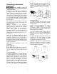
Canada. The green colored grounding ear, lug, or tab, extending from the adapter, must be connected to a permanent ground such as a properly grounded outlet box, as shown in C, Fig. 1. Grounding Instructions This machine must be grounded while in use to protect the operator from electric shock. In the event of a malfunction or breakdown, grounding provides a path of least resistance for electric current to reduce the risk of electric shock.
Unpacking Remove the packing material from the band saw. Note: Remove the plywood and bolts from the base. Inspect the machine for damage. Report any damage to your distributor and shipping agent. Move the saw to its permanent working location. The site should be dry, well lit, and have enough room to handle long stock and the service and/or adjustment of the machine from any side. Move the band saw off the skid. Clean all rust protected surfaces with a mild solvent or diesel fuel and a soft cloth.
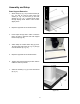
Assembly and Setup Base Support Extension 1. Attach straps (A, Fig. 1A) to extension base (B, Fig. 1A) with (2) 5/16-18 button head cap screws (C, Fig. 1A) and with (2) 5/16 flat washers (D, Fig. 1A). If needed punch holes through striping decal. NOTE: Leave screws slightly loose. 2. Repeat for opposite end of extension base. Figure 1A 3. Insert straps through slits in base of machine lining up holes in machine base with tapped holes in strap (Fig 1B) 4.
Adjusting Blade Tension 1. Disconnect machine from the power source, unplug. 2. Turn blade tension hand wheel (E, Fig. 2) counter-clockwise to tension blade, and clockwise to loosen the tension. A gauge on the upper wheel slide bracket (F, Fig. 2) indicates the approximate tension according to the width of the blade. The JWBS-16B comes with a 3/4” blade so the tension should be set at 3/4” when using this blade.
Lower Blade Guide Adjustment Disconnect machine from the power source, unplug before making any adjustments! Blade teeth are sharp! Use care when working near the saw blade. Failure to comply may cause serious injury! 1. Blade tension and tracking must be properly adjusted prior to blade guide setup. 2. The blade guard has been removed in Figure 4 for photo purposes only. Figure 3 3. Loosen the socket head cap screws (G, Fig. 4) and position the blade guide assembly (H, Fig.
Mounting the Table 1. Mount the trunnion support bracket (A, Fig. 5) to the bandsaw with four 5/16” x 1-1/2” hex cap bolts, and four 5/16” lock washers (B, Fig. 5). 2. Remove the round table insert (C, Fig. 5) found where the blade goes through the table. Also, remove the table pin (D, Fig. 5) found on the side of the table. 3. Slide saw blade through slot in table where the table pin was located.
Rail Assembly (optional accessory) 1. Attach the front rail (A, Fig. 8) to the cast iron table with two 1/4” x 5/8” hex cap bolts, two 1/4” lock washers, and two 1/4” flat washers. Bolts should be in approximately the center of the slot. Hand tighten only at this time. 2. Attach the rear rail (B, Fig. 8) to the table with two 1/4” x 5/8” hex cap bolts, two 1/4” lock washers, and two 1/4” flat washers. Bolts should be in approximately the center of the slot. Hand tighten only at this time. Figure 8 3.
4. Check the clearance between the table and the fence. The gap should be the same at the front of the table as it is at the rear. If the gap width is different, adjust the foot at the rear of the fence until the gap width is the same, Figure 11. Note: You can also adjust the front rail, or rear rail up, or down to achieve the proper clearance. 5. With a square verify the fence face is perpendicular to the table top. If it is not the front rail will need to be adjusted parallel to the table top.
Tilting the Table 1. Disconnect the machine from the power source, unplug. 2. Loosen the lock knobs (A, Fig. 13). 3. Tilt table up to 45 degrees to the right, or up to 10 degrees to the left. 4. Tighten the lock knobs. Figure 13 Note: Table stop bolt (B, Fig. 13) must be removed to tilt table to the left. Height Scale Adjustment 1. Disconnect the machine from the power source, unplug. 2. The upper blade guide should be set about 1/8” above the material to be cut. 3.
Changing Blades Disconnect machine from the power source, unplug! Blade teeth are sharp! Use care when handling the saw blade. Failure to comply may cause serious injury! 1. Remove the table insert (A, Fig. 16), and table pin (B, Fig. 16). 2. Lower the upper blade guide assembly about half way by loosening the lock knob (F, Fig. 17) and turning the hand wheel (G, Fig. 17). 3. Loosen socket head cap screw (C, Fig. 16) and slide the blade guide assembly back as far as it will go. 4.
Replacing V-Belt 1. Disconnect the machine from the power source. 2. Release blade tension by turning blade tension hand wheel clockwise. 3. Release belt tension by loosening the two hex cap bolts (A, Fig. 19). Raise the motor and tighten hex cap bolts to take the tension off the belt. 4. Open the lower wheel door and remove hex nut, and washer (B, Fig. 20). Figure 19 5. Remove the wheel (C, Fig. 21).
Electrical Connections All electrical connections must be done by a qualified electrician! Failure to comply may result in loss of property and/or serious injury! The JWBS-16B is rated at 1-1/2 HP, 1Ph, 115V/230V, prewired 115V. The bandsaw comes with a 115V plug (A, Fig. 22). If you switch the motor to 230V a plug needs to be purchased for the bandsaw that matches the 230V outlet you intend to use. Confirm power at the site is the same as the saw before making any electrical connections.
Troubleshooting Trouble Saw stops or will not start Does not make accurate 45° or 90° cuts Possible Cause 1. 2. 1. 2. 3. Saw unplugged Fuse blown or circuit breaker tripped Cord damaged 1. Stop not adjusted correctly 1. 2. Angle pointer not set accurately Miter gauge out of adjustment 2. 3. Check blade with square and adjust stop Check blade with square and adjust pointer Adjust miter gauge 1. Check and adjust fence 2. Fence not aligned with blade Warped wood 2. 3. 4.
Upper Wheel Assembly Index No. Part No. Description Size Qty 1 ...............JWBS16B-101 .........Saw Body ............................................................. .................................... 1 2 ...............TS-0152011 .............Carriage Bolt ........................................................ 5/16-18x1.................... 6 3 ...............JWBS18-103............Upper Wheel Bracket........................................... .................................... 2 4 ............
Upper Wheel Assembly 21
Lower Wheel and Motor Assembly Index No. Part No. Description Size Qty 1 ...............JWBS18-201N .........Bearing Base ....................................................... .................................... 1 2 ...............JWBS20-62..............Adjusting Bolt ....................................................... .................................... 4 3 ...............TS-0720091 .............Lock Washer ........................................................ 3/8 ...........................
Lower Wheel and Motor Assembly Index No. Part No. Description Size Qty 52 .............TS-0680031 .............Flat Washer.......................................................... 5/16 ............................. 8 53 .............TS-0720081 .............Lock Washer ........................................................ 5/16 ............................. 2 54 .............TS-0561021 .............Hex Nut ................................................................ 5/16-18........................
Blade Guides Assembly Index No. Part No. Description Size Qty 1 ...............TS-0051051 .............Hex Cap Screw .................................................... 5/16-18x1.................... 4 2 ...............TS-0720081 .............Lock Washer ........................................................ 5/16 ............................. 4 3 ...............TS-0680031 .............Flat Washer.......................................................... 5/16 ............................. 8 4 .........
Blade Guides Assembly 25
Table Assembly Index No. Part No. Description Size Qty 1 ...............JWBS16-401............Table .................................................................... .................................... 1 2 ...............JWBS20-144............Table Insert .......................................................... .................................... 1 3 ...............JWBS20-145............Roll Pin................................................................. Ø3x10 ......................... 1 4 .
Table Assembly 27
Fence & Miter Assembly (optional accessory) Index No. Part No. Description Size Qty 1 ...............JWBS18-401............Lock Knob ............................................................ .................................... 1 2 ...............TS-0680021 .............Flat Washer.......................................................... 1/4 ............................. 11 3 ...............JWBS18-403............Miter Gauge Body ................................................ ......................
Fence & Miter Assembly (optional accessory) 29
Wiring Diagram 30
Notes 31
WMH Tool Group, Inc. 2420 Vantage Drive Elgin, Illinois 60124 Phone: 800-274-6848 www.wmhtoolgroup.