This Manual is Bookmarked This Manual is Bookmarked Owner's Manual Cold Saw Models: FK350-2, FK350-2SX, FK350-4, FK350-4SX FK350 WMH TOOL GROUP 2420 Vantage Drive Elgin, Illinois 60124 Ph.: 800-274-6848 www.wmhtoolgroup.com FK350-SX Part No.
Warranty and Service WMH Tool Group, Inc., warrants every product it sells. If one of our tools needs service or repair, one of our Authorized Service Centers located throughout the United States can give you quick service. In most cases, any of these WMH Tool Group Authorized Service Centers can authorize warranty repair, assist you in obtaining parts, or perform routine maintenance and major repair on your WILTON® tools. For the name of an Authorized Service Center in your area call 1-800-274-6848.
Table of Contents Warranty and Service.................................................................................................................................... 2 Table of Contents.......................................................................................................................................... 3 Warnings ....................................................................................................................................................... 4 Introduction .....
Warnings 1. Read and understand the entire owner's manual before attempting assembly or operation. 2. Read and understand the warnings posted on the machine and in this manual. Failure to comply with all of these warnings may cause serious injury. 3. Replace the warning labels if they become obscured or removed. 4. The cold saw is designed and intended for use by properly trained and experienced personnel only.
23. Give your work undivided attention. Looking around, carrying on a conversation and “horse-play” are careless acts that can result in serious injury. 24. Maintain a balanced stance at all times so that you do not fall into the blade or other moving parts. Do not overreach or use excessive force to perform any machine operation. 25. Use the right tool at the correct speed and feed rate. Do not force a tool or attachment to do a job for which it was not designed.
Introduction The FK350 and FK350-SX are circular saws designed to provide a reliable solution to the needs of machine shops and production environments that work with steel or iron. The FK350 is manually operated: after clamping the material in the vise, the operator presses the trigger handle starting the blade, and brings the operating lever downward to cut the material. The SX offers both semi-auto and manual mode.
FK350 Features FK350 Cold Saw FK350-SX Cold Saw 7
Features Miter Cutting Head The miter cutting head is the unit that cuts the material and consists of a cast iron base, blade support unit and guard, transmission unit, and motor. The depth of cut is set by adjusting the depth cut stop. The miter cutting head swivels and locks into -45º, 90º, and +45º by means of a locking mechanism. Depressing the mechanism overrides the lock, permitting the head to adjust to any position between -45º and +45q.
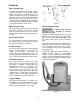
Installation Electrical Connections Unpacking the machine All electrical connections must be done by a qualified electrician. All adjustments or repairs must be done with the machine disconnected from the power source, unplugged. Failure to comply may result in serious injury! Do not handle the packed machine using slings. To install the machine, first remove the packing, paying particular attention not to cut any electric wires or hydraulic hoses. Lift using straps (Figure 3).
Control Panel – FK350-SX Controls Emergency – Emergency Stop: This turns off the controls, and the machine. When used, it requires that “Control On” button be pushed. Control Panel – FK350 The Control Panel (Figure 4) is located on the front the cabinet stand and consists of the Power and High/Stop/Low switches, described below. Vise – Open/Close (Manual mode Power Switch – The Power switch has two positions, Off and On. Start – In manual mode, this starts the saw blade.
Operation Before using the machine: Check that safety devises (ex., blade guards) are in position and work perfectly and that personal safety requirements are complied with. Check the sharpness of the blade and verify coolant flow. FK350-SX To operate machine, FK350 1. Clear the Emergency Stop. 1. Make sure the work piece is securely clamped in the vise. 2. Press Control On. 3. Select the desired blade speed. 2. Turn the power on (A, Fig. 8). 4. Select Manual or Semi-auto. 3.
Miter Adjustment The adjust the miter position follow the steps below while referring to Figure 10: 1. Move the miter position lock (A) to the right to release. 2. Adjust the head to the desired angle ranging from –45º to +45º by pushing on the back of the motor to the right or left. The miter position is shown on the scale (B). 3. A detent mechanism locks the head in the -45º, 90º and +45º positions and will prevent the head from rotating.
Air Prep Unit – FK350-SX only Maintenance The Air Prep Unit regulates the air pressure supplied to the saw. It is located in the cabinet stand and is accessible through the access door located below and to the left of the control panel. Referring to Figure 13, it consists of a pressure regulator, pressure gauge, water trap and lubricator. Air pressure (90lbs. minimum) is supplied to the air intake valve located near the bottom of the cabinet on the left side.
Lubrication For long life and trouble free operation, it is essential that this machine is kept well lubricated. The vice and leadscrew should be oiled daily. Pivot joints and bearings should be greased weekly Check the gearbox oil level weekly, full level is top of sight glass with head in full up position. The gearbox oil should be changed annually, and the hydraulic fluid [FK350-SX] should be changed annually. Recommended Lubricants: Gearbox Use Texaco Meropa 460 or equivalent.
Blade Selection When using the FK350 cold saw, it is important to select the correct type of blade for the material to be cut. This section explains the limitations and specific applications of the different types of blades. General Characteristics: Fine Tooth Pitch --used for thin wall materials such as sheet steel, tubes and profiles Coarse Tooth Pitch --used for large crosssections -- for soft materials (aluminum alloys and soft alloys in general).
Blade Structure For non--ferrous metals, it is common to use circular saws with brazed hard metal HM cutting edge, consisting of a disc made of alloy tool steel (71Cr1) on which the shape of the teeth and the seats for the cutting edges are made of Widia K10. These saws have shown excellent wear resistance but low resistance to impact, which is in any case a minor problem with nonferrous materials.
Figure 17 Figure 19 Short swarf material such as brass, bronze, aluminum and hard cast iron require smaller cutting angles because the swarf becomes crushed immediately and the rake angle has little effect during the cutting stage.
Troubleshooting Troubleshooting – Blade and Cutting Problems Problem Teeth breaking Rapid tooth wear Broken blade Probable Cause Solution Incorrect lubricant/coolant fluid Ensure proper coolant flow. Material too hard Check the cutting speed, feed speed and air pressure parameters and the type of blade you are using. Disc not worn--in correctly With a new blade it is necessary to start cutting at half feeding speed.
Troubleshooting – Machine Fault & Operating Problems Problem Probable Cause Solution Electrical power supply Check: the phases; the cables; the plug; the socket. Also check that the motor connections are in place. Transformer Check that the voltages are present both on the input and output. Otherwise replace. Contactor Check that the phases in it are present both on the input and output, that it is not jammed, that it closes when powered and that it is not causing short circuits.
Head Assembly – FK350 & FK350-SX Index No. Part No. Description Size Qty 1 ...............FK350-201 ...............Head Body ........................................................... .................................... 1 2 ...............FK350-202 ...............Spindle ................................................................. .................................... 1 3 ...............FK350-203 ...............Spindle Housing................................................... ....................
Head Assembly – FK350 & FK350-SX 21
Power Feed Assembly – FK350-SX Index No. Part No. Description Size Qty 1 ...............FK350SX-701 ..........Spring Bracket A .................................................. .................................... 1 2 ...............FK350SX-702 ..........Spring Bracket B .................................................. .................................... 1 3 ...............FK350SX-703 ..........Converter Bracket ................................................ ....................................
Power Feed Assembly – FK350-SX 23
Stock Stop Assembly Index No. Part No. Description Size Qty 1 ...............FK350-501 ...............Block .................................................................... .................................... 1 2 ...............FK350-502 ...............Shaft..................................................................... .................................... 1 3 ...............FK350-503 ...............Stop Rod .............................................................. ......................
Stand Assembly – FK350 Index No. Part No. Description Size Qty 1 ...............FK350-601 ...............Cabinet Stand ...................................................... .................................... 1 2 ...............FK350-602 ...............Coolant Pump ...................................................... .................................... 1 3 ...............FK350-603 ...............Cam Switch .......................................................... ..................................
Stand Assembly – FK350-SX Index No. Part No. Description Size Qty 1 ...............FK350SX-601 ..........Cabinet Stand ...................................................... .................................... 1 2 ...............FK350SX-602 ..........Foot Switch (Optional) ......................................... .................................... 1 3 ...............FK350-603 ...............Cam Switch .......................................................... ....................................
Stand Assembly – FK350-SX 27
Base Assembly – FK350 Index No. Part No. Description Size Qty 1 ...............FK350-101 ...............Base ..................................................................... .................................... 1 2 ...............FK350-102 ...............Hinge Body........................................................... .................................... 1 3 ...............FK350-103 ...............Locking Mount...................................................... .............................
Base Assembly – FK350 29
Base Assembly – FK350-SX Index No. Part No. Description Size Qty 1 ...............FK350-101 ...............Base ..................................................................... .................................... 1 2 ...............FK350-102 ...............Hinge Body........................................................... .................................... 1 3 ...............FK350-103 ...............Locking Mount...................................................... ..........................
Base Assembly – FK350-SX 31
Manual Vise Assembly – FK350 Index No. Part No. Description Size Qty 1 ...............FK350-301 ...............Base ..................................................................... .................................... 1 2 ...............FK350-302 ...............Vise Jaw............................................................... .................................... 2 3 ...............FK350-303 ...............Tip ........................................................................ ...........
Manual Vise Assembly – FK350 33
Power Vise Assembly – FK350-SX Index No. Part No. Description Size Qty 1 ...............FK350-301 ...............Base ..................................................................... .................................... 1 2 ...............FK350-302 ...............Vise Jaw............................................................... .................................... 1 3 ...............FK350-303 ...............Tip ........................................................................ .........
Power Vise Assembly – FK350-SX File 27 35
Guard Assembly – FK350 & FK350-SX Index No. Part No. Description Size Qty 1 ...............FK350-401 ...............Guard A................................................................ .................................... 1 2 ...............FK350-402 ...............Guard B................................................................ .................................... 1 3 ...............FK350-403 ...............Guard C................................................................ ..............
Guard Assembly – FK350, FK350-2SX 37
In-Feed Table Assembly Index No. Part No. Description Size Qty 1 ...............FK350-701 ...............Bracket ................................................................ .................................... 1 2 ...............FK350-702 ...............Stand.................................................................... .................................... 1 3 ...............FK350-703 ...............Leveling Foot ....................................................... ........................
Out-Feed Table 1 ...............FK350-801 ...............Guide Block.......................................................... ................................. EA 2 ...............FK350-802 ...............Guide Rail ............................................................ ................................. EA 3 ...............TS-1502051 .............Socket Head Cap Screw...................................... M5x20 ...................... EA 4 ...............FK350-804 ...............Stopper Base .........
Pneumatic Drawing – FK350-SX Wiring Diagram – FK350 40
Wiring Diagram – FK350-SX 41
--NOTES-- 42
--NOTES-- 43
WMH Tool Group 2420 Vantage Drive Elgin, Illinois 60124 Phone: 800-274-6848 www.wmhtoolgroup.