
Datasheet

127
08.11
D
P
P
1
P
0
P
2
F
d
P
P
1
H
1
H
P
0
d
P
2
F
t
D
0
W
2
Vh
W
0
P
1
P
2
P
0
P
H
1
H
W
1
W
d
F
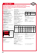
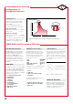
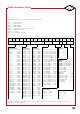
Diagram 1:
PCM 2.5/5/7.5mm
Diagram 3: PCM 22.5 and 27.5*mm
*PCM 27.5 taping possible with two feed holes between components
Diagram 2: PCM 10/15 mm
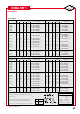
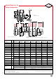
Dimensions for Radial Taping
Designation Symbol PCM 2.5 taping PCM 5 taping PCM 7.5 taping PCM 10 taping* PCM 15 taping* PCM 22.5 taping PCM 27.5 taping
Carrier tape width W 18.0
p0.5
18.0
p0.5
18.0
p0.5
18.0
p0.5
18.0
p0.5
18.0
p0.5
18.0
p0.5
Hold-down tape width W
0
6.0
for hot-sealing
6.0
for hot-sealing
12.0
for hot-sealing
12.0
for hot-sealing
12.0
for hot-sealing
12.0
for hot-sealing
12.0
for hot-sealing
adhesive tape adhesive tape adhesive tape adhesive tape adhesive tape adhesive tape adhesive tape
Hole position W
1
9.0
p0.5
9.0
p0.5
9.0
p0.5
9.0
p0.5
9.0
p0.5
9.0
p0.5
9.0
p0.5
Hold-down tape position W
2
0.5 to 3.0 max. 0.5 to 3.0 max. 0.5 to 3.0 max. 0.5 to 3.0 max. 0.5 to 3.0 max. 0.5 to 3.0 max. 0.5 to 3.0 max.
Feed hole diameter D
0
4.0
p0.2
4.0
p0.2
4.0
p0.2
4.0
p0.2
4.0
p0.2
4.0
p0.2
4.0
p0.2
Pitch of component P 12.7
p1.0
12.7
p1.0
12.7
p1.0
25.4
p1.0
25.4
p1.0
38.1
p1.5
3
*
8.1
p1.5
or 50.8
p1.5
cumulative pitch
cumulative pitch
cumulative pitch
cumulative pitch
cumulative pitch
cumulative pitch
cumulative pitch
Feed hole pitch P
0
12.7
p0.3 error max.
12.7
p0.3 error max.
12.7
p0.3 error max.
12.7
p0.3 error max.
12.7
p0.3 error max.
12.7
p0.3 error max.
12.7
p0.3 error max.
1.0 mm/20 pitch
1.0 mm/20 pitch
1.0 mm/20 pitch
1.0 mm/20 pitch
1.0 mm/20 pitch
1.0 mm/20 pitch
1.0 mm/20 pitch
Feed hole centre
P
1
5.1
p0.5
3.85
p0.7
2.6
p0.7
7.7
p0.7
5.2
p0.7
7.8
p0.7
5.3
p0.7
to pin
Hole centre to
P
2
6.35
p1.3
6.35
p1.3
6.35
p1.3
12.7
p1.3
12.7
p1.3
19.05
p1.3
19.05
p1.3
component centre
Feed hole centre to bottom
H
16.5
p0.3
16.5
p0.3
16.5
p0.5
16.5
p0.5
16.5
p0.5
16.5
p0.5
16.5
p0.5
edge of the component
18.5
p0.5
18.5
p0.5
18.5
p0.5
18.5
p0.5
18.5
p0.5
18.5
p0.5
18.5
p0.5
Feed hole centre to top
H
1
H+H
component
< H
1
H+H
component
< H
1
H+H
component
< H
1
H+H
component
< H
1
H+H
component
< H
1
H+H
component
< H
1
H+H
component
< H
1
edge of the component 32.25 max. 32.25 max. 24.5 to 31.5 25.0 to 31.5 26.0 to 37.0 30.0 to 43.0 35.0 to 45.0
Pin spacing at
F 2.5
p0.5
5.0
+0.8
7.5
p0.8
10.0
p0.8
15
p0.8
22.5
p0.8
27.5
p0.8
upper edge of carrier tape
–0.2
Pin diameter d 0.4
p0.05
0.5
p0.05
„
0.5
p0.05
or
0.6
–0.05
„
0.5
p0.05
or
0.6
–0.05
0.8
–0.05
0.8
–0.05
0.8
–0.05
Component alignment Dh p 2.0 max. p 2.0 max. p 3.0 max. p 3.0 max. p 3.0 max. p 3.0 max. p 3.0 max.
Total tape thickness t 0.7
p0.2
0.7
p0.2
0.7
p0.2
0.7
p0.2
0.7
p0.2
0.7
p0.2
0.7
p0.2
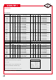
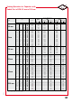
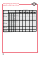
ROLL/AMMO AMMO
Package
(see also page 128)
Unit see details page 130.
Dims in mm.
„
Diameter of pins see General Data. Please clarify customer-specific deviations with the manufacturer.
* PCM 10 and PCM 15 can be crimped to PCM 7.5.
Position of components according to PCM 7.5 (sketch 1). P
0
= 12.7 or 15.0 is possible
REEL
P 360 max.
B
52 p2 depending on
P 30 p1 58 p2 comp. dimensions
52 p2 54 p2 depending
REEL
P 360 max.
B 58
p2
or
REEL
P 500 max.
B 60
p2 on PCM and
P 30 p1
66
p2
P 25 p1
68
p2 component dimensions
+0.06 +0,06 +0,08 +0,08 +0.08
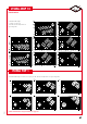
Typical Dimensions for
Taping Configuration