
Installation manual


WIN SERIES INSTALLATION MANUAL
12
JP7: Hardware interrupt terminator. Install on the first VLC ONLY!
JP8: Sets audio source
in RJ-14 jacks (default)
JP101-JP401: Lowers ring detection threshold on corresponding port if jumper is installed. On
D41D, rev. 3 cards only. DO NOT INSTALL THESE JUMPERS!
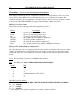
SW1: Sets the offset address and default line state for each board
These switches are set at the factory and if you only have a single VLC in your system, it will
generally not have to be touched. If, however, you install additional VLC's it will be necessary to
configure the switches on each board to identify the board #. The board with the lower address
will be board 1, etc….
SW1-1, 1-2, 1-3 control the base address of the WIN Speech boards. SW1-4 controls initial (off-
line) state of the telephone lines.
SW1 position
1 2 3 4 Board # Offset Address From BASE (HEX)
* * * * 1 0000 Factory setting
*
* * * 2 2000
*
* * * 3 4000
* *
* * 4 6000
*
* * * 5 8000
* *
* * 6 A000
NOTE: For the digital type Dialogic boards (SL-1, Mitel, and Norstar), switch 4 MUST be set to
OFF. This stops the PBX from taking the port out-of-service when the system is off line.
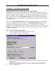
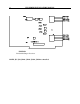
Figure 1 shows the position of the dip switches and jumpers on a Dialogic D21 or 41D speech
card.
Note: The D21 card supports only two ports. Line 1 tip and ring is on J1 and Line 2 tip and
ring is on J2.