
Specification


5006140-BTG-C-0716
Johnson Controls Unitary Products 39
TYPICAL INSTALLATION
NOTE:
Ensure a minimum of
24” clearance between
any two units.
10” CLEARANCE
AROUND PERIMETER
(6” clearance
permissible on one
side only, see
Alternative
Installation
Clearances.)
48” OVERHEAD CLEARANCE
MINIMUM 18” SERVICE ACCESS CLEARANCE
Maintain minimum clearance on one side of access panel.
WEATHERPROOF
DISCONNECT
SWITCH
NEC CLASS 1 WIRING
THERMOSTAT
NEC CLASS 2 WIRING
TO FURNACE OR
AIR HANDLER
TERMINAL BLOCK
NEC CLASS 2 WIRING
CONTROL
ACCESS
PANEL
SEAL OPENINGS
Use permagum or equivalent.
NOTE:
All outdoor wiring
must be weatherproof.
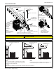
5 SNOW PUMP-UPS
Use in deep snow areas
with fth pump-up under
center of compressor.
A0260-002
3 BRACES
Use for wall mount with
center brace under
center of compressor.
NOTE:
Ensure adequate
wall support.
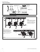
CAUTION: Special care must be taken to avoid recirculation of discharge air through condenser coil.
CAUTION
Care must be taken to prevent ice from damaging the unit. Damage may occur from ice falling onto unit from a sloped roof or from a vertical drip
line due to a partial overhang.
!
A0291-001
(Refer to CAUTION above.)
INSTALLATION ACCEPTABLE
INSTALLATION ACCEPTABLE
INSTALLATION NOT RECOMMENDED
NO OVERHANG COVERING UNIT
OVERHANG COMPLETELY
COVERING UNIT
OVERHANG PARTIALLY
COVERING UNIT
48” MINIMUM
OVERHEAD
CLEARANCE
NOTE:
The unit must be installed on a solid base above the grade.
The base must not be able to settle or shift causing strain on
refrigerant lines and possible leaks.
NOTE:
Install unit on flat surface. If installation surface is sloped, ensure
that unit slopes away from house structure at 1/4” per foot.
CAUTION:
Special care must be taken to avoid recirculation of discharge air through condenser coil.
(Refer to CAUTION above.)