
Installation Guide

HamiltonHomeProducts CanalWinchester,OH4311061MH0037A
INSTALLATION MANUAL
DOWNFLOW SINGLE AND TWO STAGE ELECTRIC FURNACE WITH:
FACTORY INSTALLED ELECTRIC HEAT, OR
NO HEAT MODELS WITH FIELD INSTALLED ELECTRIC HEAT KITS
MODELS: WE30 SERIES
LIST OF SECTIONS
1 – General 1 7 – Line Voltage Wiring 8
2 – Safety 3 8 – Field Installed Heat Kit 12
3 – Downflow Return Air and Clearance Requirements 4 9 – Thermostat Wiring and Connections 13
4 – Downflow Supply Air and Duct Connector Installation 5 10 – Motor, Blower and Furnace Start Up 16
5 – Furnace Installation 7 11 – Final System Checkout 17
6 – Upflow Configuration 8 12 – Wiring Diagrams 18
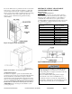
LIST OF FIGURES
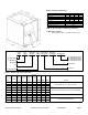
1 – Furnace Dimensions 2 16 – Separate Thermostats, Separate Furnace Wiring Diagram 14
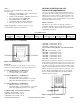
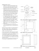
2 – Closet Clearances 4 17 – Separate T’stat, Separate Furnace & Trans Wiring Diagram 14
3 – Typical Closet Installations 4 18 – Same T’stat, Separate Furnace, Trans and Heat Pump 14
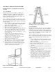
4 – Typical Alcove Installations 5 19 – Same T’stat, Separate Furnace, Trans and Cool Unit 14
5 – Clearance – Access for Service 5 20 – Single Stage Heat / Cool T’stat, with a Two Stage Furnace 15
6 – Duct Connector Depths 5 21 – Two Stage Heating / Cooling T’stat, Furnace Connections 15
7 – Duct Connector and Floor Base Installations 6 22 – Typical Two Stage Heat Pump/Heating/Cooling T’stat, Furnace 16
8 – Duct Connector Measurements 6 23 – Constant Torque motor Terminals 17
9 – Duct Connector Installation in the floor 6 24 – Blower Assembly and Blower Deck 17
10 – Return Air Grille Frame Assembly 7 25 – Wiring Diagram No Heat Model w/ Blower Motor 18
11 – Return Air Filter Frame Assembly 7 26 – Wiring Diagram 10 kW, w/ C.T. Blower Motor 19
12 – Typical Upflow Installation 8 27 – Wiring Diagram 12 kW, w/ C.T. Blower Motor 20
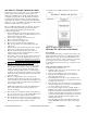
13 – Control Box Component Locations 11 28 – Wiring Diagram 15 kW w/ C.T. Blower Motor 21
14 – Control Box Cover and Circuit Breaker Location 11 29 – Wiring Diagram 20 kW w/ C.T. Blower Motor 22
15 – Control Box Power, Low Voltage Wire Locations 13
LIST OF TABLES
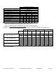
1 – Electric Furnace Model Specifications 2 8 – Electrical Data 10
2 – Model Nomenclature 2 9 – Field Installed Electric Heat Kit Model Numbers 12
3 – Optional Cooling Cabinets and Return Air Grille 2 10 – Field Installed Electric Heat Kit Model Nomenclature 12
4 – Clearances to Combustibles 4 11 – Low Voltage Wire Gauge and Max Lengths 13
5 – Duct Connectors 5 12 – Recommended Heat/Cool T’stat Wire Color Code 15
6 – Wiring Requirements – Single Branch Circuit 9 13 – Recommended Heat/Cool/HP T’stat Color Code 15
7 – Wiring Requirements – Dual Branch Circuit 10 14 – Constant Torque (C.T.) Motor Terminal Connections 16
SECTION I: GENERAL
The following list includes important facts and information
regarding the electric furnace and its inclusions.
1. Furnace is rated at 240 volts AC at 60 Hertz
2. Furnace is the same size for all models
3. Four-wire thermostat operation for heating and cooling
4. A/C ready furnaces equipped with blower for A/C or
Heat Pump operation
5. Holding Strap furnished with furnace
6. This furnace is designed for downflow application
7. This furnace must not be operated without furnace door
installed
NOTE: This furnace and its components listed on the
A/C and Heat Pump equipment sticker were listed in
combination as a system by ETL for the United States.
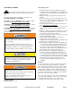
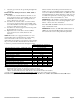
Blower Speed Tap Description
Tap 5 – High Speed – Cooling or Heat Pump Operation
Tap 4 – Med-High Speed – Cooling or Heat Pump Operation
Tap 3 – Medium Speed – Cooling or Heating Operation
Tap 2 – Med-Low Speed – Heating Operation
Tap 1 – Low Speed – Constant Circulation Operation Only.
Tap 1 air circulation is around 200 CFM. This is not enough
air flow for heating, cooling or heat pump operation. If Tap 1
is used for cooling the evaporator will freeze up. If Tap 1 is
used for heating with electric heat the limits will open in a
very short time frame.
DO NOT USE SPEED TAP 1 FOR HEATING OR
COOLING!
SAVE THIS MANUAL FOR FUTURE
REFERENCE