
Manual

Page 1 of 4
006090 Rev R Date 11-08-11 JWC
DO NOT
LIFT OR CHANGE CHAIR POSITION BY USING THE LEGREST.
THIS COULD CAUSE INJURY TO USER OR DAMAGE TO THE RECLINE MECHANISM AND WILL VOID WARRANTY.
ALWAYS CHANGE POSITION FROM BACK OF CHAIR.
1. READ AND FOLLOW ALL DIRECTIONS.
2. NEVER use tray as a restraint.
3. DO NOT put hands, feet or clothing into any openings when changing recliner positions. Attendant MUST confirm
that users hands & feet are clear of moving parts when changing recliner positions or INJURY MAY RESULT.
4. Stay clear of the recline mechanisms.
5. Periodically, recheck tightness of all nuts, bolts and screws.
6. NEVER use the trays or chair arms or backrest or legrest as a seat; SERIOUS INJURY MAY OCCUR.
7. Chair MUST be in full upright position with casters locked when a patient enters or exits chair.
8. NEVER allow a patient to exit a reclined chair with position-lock engaged or SERIOUS INJURY MAY RESULT.
9. Lock casters at all times, except when transporting chair.
10. Chair must ALWAYS be positioned on a level surface.
11. DO NOT use recliner for Transporting in or with ANY type of vehicle or trailer. Winco recliners have not been
tested or approved for use by an occupant in any type of vehicle or trailer.
12. Immediately remove from service; Any recliner with broken recline mechanisms, torn upholstery, or other
mechanical or visible damage.
13. USE ONLY WINCO AUTHORIZED REPLACEMENT PARTS.
14. NEVER EXCEED the recommended weight capacity of 275 lbs. (124.7 kg).
15. SAVE THESE INSTRUCTIONS for future reference and training.
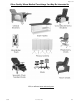
5251-525S
5261-526S
Convalescent Recliner
CUSTOMER INSTRUCTIONS
Tools required:
Scissors or box cutter to aid in removal of packing material
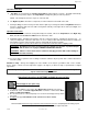
Install the Back:
1. After checking your product for any shipping damage, chair needs
to be positioned upright on level surface. Remove packing
material & hardware. Cut tape & plastic with scissors, being
careful not to damage upholstery.
2. Slide the Back Frame over the 7/8” tubes of the Seat Frame.
(FIG. 1 & 1A)
NOTE: To ease assembly, spray the Seat Frame Rail ends
with WD-40 (or similar lubricant approved by your facility).
3. Depress the ¼” Snap Button in Seat Frame while pushing
down on one side of Back Frame. (FIG. 1 & 1A)
4. Repeat procedure on opposite side until both Snap Buttons are snapped into corresponding holes of Back
Frame. NOTE: Snap buttons must protrude out of holes on back frame. (FIG. 1A)
PLEASE READ AND FAMILIARIZE YOURSELF WITH ALL INSTRUCTIONS BEFORE USING THIS PRODUCT.
If you have trouble understanding these instructions contact your dealer or Winco customer support, (800) 237-3377
before attempting to use this product; otherwise injury may occur.
5251-525S-5261-526S Wei
g
ht Ca
p
acit
y
= 275 lbs.
(
124.7 k
g
.
)
PLEASE READ AND FAMILIARIZE YOURSELF WITH
A
LL INSTRUCTIONS BEFORE PROCEEDING WITH ASSEMBLY
Winco assumes no responsibility for damage or injury caused by improper assembly,
installation, use, or maintenance of these products.
FIG. 1A
FIG. 1