
Manual


381339–211 E
ASCO POWER TECHNOLOGIES L.P. 50 Hanover Road, Florham P ark, New Jersey 07932 USA www.asco.com
Automatic Transfer Switches
forAccessory 44
Strip Heater
Accessory 44 Strip Heater is designed t o keep humidity
and/or temperature within the ATS enclosure at acceptable
levels. This accessory consists of a mounting bracket with
strip heater, thermostat, and terminal block. A transformer
with fuses is included when the power for the assembly is
derived from the ATS. The 120 V ac customer powered
assembly does not include a transformer. This accessory is
available factory installed or in kit form. If already installed,
turn the thermostat’s dial to required setting.
DANGER: De–energize all power to the
Transfer Switch before opening the enclosure.
Hazardous voltage capable of causing shock,
burns, or death is used in this switch.
Mounting
1. After de–energizing both Normal and Emergency
power sources and the Load, open the enclosure door.
Carefully use a voltmeter to verify that all power is
de–energized at the Transfer Switch power terminals
2. Hole Drilling Data Sheets are shown in this publication.
They are not drilling templates
.Theyspecifythe
locations and sizes of the strip heater assembly
mounting holes for each ampere rat ing size ATS. Drill
two holes into the enclosure as indicated.
CAUTION: Protect th e Transfer Switc h from
metal c h ips when drilling the holes. Clean up all
debris inside the enclosure after drilling.
3. Use the hardware supplied in the kit to mount the
bracket to the inside of the encl osure. The thermostat
should face the front of the enclosure after m ounting the
assembly.
dial
turn counterclockwise
to lower temperature
turn clockwise
to raise temperature
thermostat
thermostat
heater
transformer
with fuses
mounting
holes
DANGER: De–energize the conductors
before ma king any connections. Open the
Normal and Emergency source circuit breakers
and be sure that the load is also de–energized.
Wiring
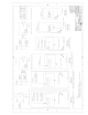
1. A Mounting Data drawing is included on the back page.
Sel ec t the approp riate wirin g diagr am and illu str atio n
accor d in g to Trans fe r Switch amp er e rating size . If 120 V
ac customer–furnished power will be used, go to step 2. If
power will be from the Transfer Switch go to step 3.
2. 120 V ac cust omer–furnished power. Run the 120 V ac
line into the enclosure and connect the wires to TB
term inal s TB–1 and TB–2 on the str ip heater assemb l y.
3. Transfer Swit ch derived power. A two–wire harness is
provided in the kit. Select the appropriate illustration on
the Mounting Data diagram (back page) according to
Transfer Switch ampere rating size. F oll ow it to connect
the harness to the Trans fer Switc h and to the strip heater
assembly. Connect one wire from transfer switch Load
term inal LA to the strip heater assemb ly’s fuse bl oc k
term inal HI; conn ec t the other wire from Load termin al
LC to terminal HF on the fuse bl oc k. Doubl e c hec k al l
wiring before continuing.
4. Turn the thermostat’s dial to desired setting. Then
close the enclosure door.
5. After the door is closed, reenergize the ATS (close
Normal and Emergency source circuit breakers and
reenergize the load). If a separate 120 V ac line was
used for the accessory, energize that line.