AUTOMATIC TRANSFER SWITCH INSTALLATION AND OPERATORS MANUAL
Read and understand all instructions in the manual before starting and operating the generator set. TABLE OF CONTENTS USING THIS MANUAL Congratulations on your choice of a Winco Automatic Transfer Switch. You have selected a high-quality, precision Automatic Transfer Switch designed and tested to give years of satisfactory service. To get the best performance from your new Automatic Transfer Switch, it is important that you carefully read and follow the operating instructions in this manual.
SAFETY INFORMATION This engine generator set has been designed and manufactured to allow safe, reliable performance. Poor maintenance, improper or careless use can result in potential deadly hazards; from electrical shock, exhaust gas asphyxiation, or fire. Please read all safety instructions carefully before installation or use. Keep these instructions handy for future reference. Take special note and follow all warnings on the unit labels and in the manuals.
TESTING POLICY: UNPACKING INSTRUCTIONS Before any Automatic Transfer Switch (A.T.S.) is shipped from the factory, it is fully checked for performance. ** NOTICE ** Rated capability of the Automatic Transfer Switch is based on engineering tests of typical units, and is subject to, and limited by, the temperature, and other conditions specified by the manufacturer. When unpacking the Automatic Transfer Switch, be sure to inspect it carefully for freight loss or damage.
AUTOMATIC TRANSFER SWITCH SIZES MODEL VOLTAGE 110/60ATS-3/C ATS-4/D 100/100 ATS-17/D 100/100 ATS-18/B 100/100 ATS-18/B 225/225 ATS-4/D 225/225 ATS-17/D 225/225 230/150ATS-3/C 230/150ATS-4/D 230/150ATS-17/D ATS-4/D 400/300 ATS-17/D 400/300 400/320ATS-3/C 120/240 120/208 120/240 277/480 277/480 120/208 120/240 120/240 120/208 120/240 120/208 120/240 120/240 CONTACTOR SIZE PH LINE GEN.
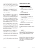
************* ***** DANGER ***** ************* Be certain the operation selector switch on the front of the A.T.S. Control is in the “stop” position and the main power switch “off”. For your own protection, verify these important safety precautions yourself with reliable instruments before proceeding. FIGURE 5 A.C. ELECTRICAL CONNECTIONS ************* ***** WARNING ***** ************* A FUSED DISCONNECT/CIRCUIT BREAKER MUST BE INSTALLED BETWEEN THE GENERATOR AND THE A.T.S.
All three neutral connections are made to the appropriate neutral lugs. These lugs have been prewired common in the A.T.S. A neutral to ground bond has also been installed in the A.T.S. panel. If your system requires an isolated neutral this bond, a copper jumper strap, should be removed. If this jumper strap is removed remember to properly ground the Automatic Transfer Switch using the grounding lug provided.
If, when you finish programming the clock, you get an “EEEE” on the display, it stands for error. The most common error is that the day of operation has not been properly set at each step or a program has been turned on and not turned off. (i.e. programs not properly grouped 1& 2, 3 & 4, 5 & 6, etc.) TROUBLESHOOTING HINTS ATS PANEL WILL NOT TRANSFER TO EMERGENCY SUPPLY (GENERATOR). 1. No AC generator output from generator. 2. Broken or defective mechanical/electrical inter locks. 3.
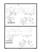
230/150ATS-4/D 230/150ATS-17/D 110/60ATS-3/C 230/150ATS-3/C 400/320ATS-3/C 0117-00 PAGE 7 60706-145
ATS-18/B 100/100 ATS-18/B 225/225 ATS-4/D 100/100 ATS-17/D 100/100 ATS-4/D 225/225 ATS-17/D 225/225 ATS-4/D 400/300 ATS-17/D 400/300 60706-145 PAGE 8 0117-00
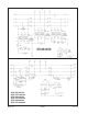
ATS PANEL OUTLINE DIMENSIONS ATS SIZE 100/50 ATS 100/100 ATS 225/100 ATS 225/225 ATS 400/225 ATS 400/300 ATS 110/60 ATS 230/150 ATS 400/320 ATS 0117-00 REF A 21.00” 22.88” 22.88” 22.88” 28.00” 28.00” 17.00” 22.90” 28.00” REF B 8.00” 14.00” 14.00” 14.00” 16.00” 16.00” 8.00” 14.00” 16.00” REF C 8.10” 10.63” 10.63” 10.63” 12.68” 12.68” 8.10” 10.63” 12.68” PAGE 9 REF D 24.25” 28.25” 28.25” 28.25” 36.00” 36.00” 20.00” 28.00” 36.00” REF E 12.375” 18.375” 18.375” 18.375” 23.88” 23.88” 12.375” 18.375” 23.
WINCO, Incorporated warrants to the original purchaser for 12 months that goods manufactured or supplied by it will be free from defects in workmanship and material, provided such goods are installed, operated and maintained in accordance with Winco written instructions. WINCO’s sole liability, and Purchaser’s sole remedy for a failure under this warranty, shall be limited to the repair of the product.