
Product Manual


Page 2 of 8
006312 Revision F Date 10-22-13 JWC
●IV Pole Attachment
Models: 5251, 5261, 5291, 5351, 5361, 5851, 5861, 6530, 6531, 6540, 6541, 6570, 6571
●Tools needed:
• Phillips Head Screwdriver
• 7/16” wrench (multiple size wrench included)
• Powered tools NOT recommended –
●Assembly Instructions
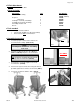
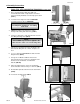
1. Locate the rear-side of the chair and place the
“IV U-Bracket Assembly” onto the rear chair
frame rail. (FIG.1)
2. Next insert the (2) 2¾” screws into the holes provided
on the bracket assembly. (FIG.2)
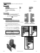
3. Secure the bracket to the chair frame using the (2)
nylon lock-nuts.
Tighten using the wrench provided. (FIG.3)
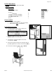
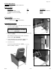
4. Insert the IV Pole.
Your chair should look like that of (FIG.4) when
assembly is complete.
FIG. 4
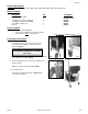
●Parts Included:
Description: Qty. Part Number
IV U-Bracket Assembly 1 227600 (LEFT)
227605 (RIGHT)
¼-20 Nylon Lock-nut (1-installed) 3 566204
¾” Phillips-head Screw (installed) 1 566504
2¾” Phillips-head Screw 2 566571
IV Pole 1
480500
FIG. 1
FIG. 3
NOTE:
Left & Right is determined – as if sitting
in the chair
FIG. 2
Pictures shown with 227600A OPTION