
Product Manual


Page 5 of 8
006312 Revision F Date 10-22-13 JWC
●IV Pole Attachment
Models: 5560, 5680, 6560, 6740, 6750, 6940, 6950, 6980, 6990
●Tools needed:
• Phillips Head Screwdriver (5560/6560 ONLY)
• ½” Wrench
(6940/6950/6980/6990 ONLY)
• 3/16” Allen Wrench
(6940/6950/6980/6990 ONLY)
• Powered tools NOT recommended –
●Assembly Instructions
5560/6560 & 6980/6990 (Right Side ONLY)
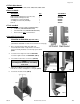
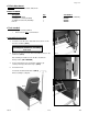
(6940/6950 & 6980/6990 Left Side ONLY instructions on next page)
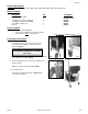
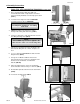
1. First, check the bracket that came with your
IV Pole Attachment Kit. Verify that the screw and
lock-nut, already installed, are in their proper location.
(FIG. 1
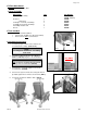
2. Locate the left or right rear side for 5560/6560.
Locate the right-rear side for 6980/6990. (FIG.2)
3. Unscrew the bolts in the cross brace. (FIG.2A)
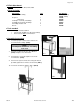
4. Place the “IV Bracket” over the cross brace,
reinsert the screws, and tighten to a snug fit. (FIG.3)
5. Your chair should look like (FIG.4).
●Parts Included:
Description: Qty. Part Number
IV Bracket Assembly (
5560, 6560, 6940, 6950) 1 227610
IV Bracket Assembly
(6980, 6990) 1 227610B
¼-20 Nylon Lock-nut (installed) 1 566204
¾” Phillips-head Screw (installed) 1 566504
IV Pole 1 480500
FIG. 2A
FIG. 2
FIG. 1
NOTE:
Left & Right is determined – as if sitting
in the chair
FIG. 4
FIG. 3