
Product Manual


Page 6 of 8
006312 Revision F Date 10-22-13 JWC
●Assembly Instructions
5680, 6740, 6750, 6940/6950 & [6980/6990 (Left Side Only)]
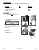
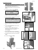
1. First, check the bracket that came with your
IV Pole Attachment Kit. Verify that the screw and
lock-nut, already installed, are in their proper location.
(FIG. 1)
2. Locate the left or right rear side for 6940/6950.
Locate the left rear side for 6980/6990.
3. CAREFULLY place the chair on it’s side &
And open the swing arm all the way. (FIG.2)
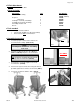
4. Using a ½” wrench & a 3/16” allen wrench unscrew
the swing-arm hinge bolt. (FIG.3)
5. Take the loosened bolt out of the arm bracket, lift
upholstered swing-arm off of frame, and place on
floor.
6. Use a ½” wrench and REMOVE the bolts from the
hinge bracket. (FIG.4)
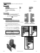
7. Line up the “IV Bracket” with the holes in the
upholstered arm. Be sure the pre-installed screw
and nut on the “IV Bracket” is towards the
bottom. (FIG.4A)
8. Place the arm bracket on top of the “IV Bracket”
and re-install the 2 bolts using a ½” wrench. (FIG.4)
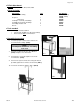
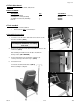
9. Re-install the upholstered arm onto the chair frame
(FIG.5)
10. Your chair should look like (FIG.6)
NOTE:
Left & Right is determined – as if sitting
in the chair
NOTE:
Some FORCE may need to be applied to the
allen wrench in order to loosen the hinge bolt
FIG. 2
FIG. 3
FIG. 4
FIG. 4A
FIG. 6
FIG. 1
FIG. 5