
Product Manual


Page 7 of 8
006312 Revision F Date 10-22-13 JWC
●IV Pole Attachment
Models: 5400, 5570, 5580, 5670, 6700, 6710
●Tools needed:
• Phillips Head Screwdriver
• Powered tools NOT recommended –
●Assembly Instructions
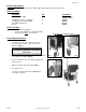
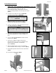
1. Locate the rear-side of the chair and remove the 2 screws
from the rear-brace (FIG.1)
2. Next, line up the holes in the IV bracket with the holes in the
rear-brace. (FIG.2)
Nut and bolt pre-installed on the IV tube should be in
down position. (FIG.2-ARROW)
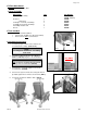
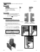
3. Secure the bracket to the chair frame using the (2)
screws previously removed in step 1. (FIG.3)
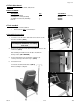
5. Insert the IV Pole.
Your chair should look like that of (FIG.4)
when assembly is complete.
●Parts Included:
Description: Qty. Part Number
IV Bracket Assembly 1 227630 (LEFT or RIGHT)
¼-20 Nylon Lock-nut (installed) 1 566204
¾” Phillips-head Screw (installed) 1 566504
IV Pole 1 480500
FIG. 1
FIG. 3
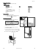
NOTE:
Left & Right is determined – as if sitting
in the chair
FIG. 2
FIG. 4