BA73A LCD TFT 15" (38.
Published by Wincor Nixdorf GmbH & Co. KG D-33094 Paderborn Bestell-Nr./Order No.
BA73A LCD TFT 15" Flat Screen User Manual Edition May 2001
MS-DOS®, Microsoft®, Windows 3.1 ®, Windows 95/98® Windows 2000®, Windows Me® and Windows NT® are registered trademarks of Microsoft Corporation, USA. PanelLink® is a registered trademark of Silicon Image Inc., USA Pentium® is a registered trademark of Intel Corp., USA PCI® is a registered trademark of the PCI Special Interest Group (SIG), USA BEETLE® is a registered trademark of the Wincor Nixdorf GmbH & Co.
Contents Introduction ............................................................................................... 1 From Point-of-Sale to Point-of-Service ....................................................... 1 Advantages at a Glance.............................................................................. 2 Unpacking and checking the Delivery Unit ................................................. 3 About this Manual..................................................................................
Resistive Touch Screen (Option) ...........................................................20 General....................................................................................................20 How to Operate .......................................................................................21 Installing and Securing the Screen into Place .....................................23 Adjustable Screen Angle ...........................................................................
Technical Data ........................................................................................ 48 Touch Screen (optional)............................................................................ 48 TFT/ LCD Screen ...................................................................................... 49 BA73A ....................................................................................................... 50 Current Consumption ...............................................................
Introduction From Point-of-Sale to Point-of-Service “The customer is king”, a motto that seems so simple and yet it demands a permanently increasing supply of goods and services, both quantitatively and qualitatively. More customer service and more customer information have transformed the point-of-sale to a point-of-service, as business transactions are becoming more complex and there are growing demands on shop assistants and personnel working on the cash till.
Advantages The low-energy, flickerfree and radiation-free colour monitor of the BA73A is an Active-Matrix-Display in TFT-technology (Thin Film Transistor). Therefore, it is well suited for multimedia applications as it offers brilliant colour representation, an excellent contrast ratio and a high display speed. The screen can be installed directly on the cashier’s desk. Furthermore, it can also be set up on the central unit of a modular BEETLE system.
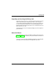
Delivery Unit Unpacking and checking the Delivery Unit Unpack the parts and check to see whether the delivery matches the information on the delivery note. The delivery comprises of the respective screen module. Controllers and data cables, necessary for operation, can be ordered separately. If damage has occurred during shipping or if the package contents do not match the delivery note, immediately inform your Wincor Nixdorf sales outlet.
BA73A Components Screen Module The screen module represents the main unit of the BA73A. It comprises of a TFT-LCD colour screen, the TFT-interface and an inverter that generates the voltage for backlighting the screen. As an option the screens are available with Touch Screen including a loudspeaker. Behind the cover on the back of the BA73A you connect the cable. Remove the cable cover by pushing it in the direction of arrow (see picture) and then taking it off upwards.
LCD-Controller-A/BA73A “Stretching” is only possible when a separate LCD controller or an adapter (“PanelLink-Bridge”) is used (“D1" Central Processing Unit with Celeron or Pentium III Processor). There is no ”stretching" with the “D2" CPU. If the display element is damaged and the liquid crystal solution leaks out onto your hands or clothing, please wash your hands or clothing immediately under running water for at least 15 minutes, using soap or alcohol.
LCD-Controller-A/BA73A The LCD-Controller-A/BA73A is a plug-in-controller with a PCI-interface. There are two connections for r r a 40-pin MDR connector with integrated COM5 output a 9-pin DSUB female (for COM6) COM5 and COM6 are only ready for operation when the optional COM board is used. The control data and data lines for the TFT LCD display are transmitted to the 50-pin MDR connector via hardware drivers and filters.
LCD-Controller-A/BA73A 6 1 40 2 9 1 5 Panel of LCD- Ccontroller-A/BA73A COM5/ COM6 1 4 Speaker Connector Jumper B3 B2 B1 BIOS BA73A Connector incl. COM5, LCD Interface and Loudspeaker MDR Connector (40-pin) COM6 resp.
Capacative Touch Screen (Option) General The TFT Touch Screen works according to the principle of a change in analog capacitance. It has a glass screen with a transparent, thin-film overlay on the surface. This is fully sealed and protected by a further layer of clear glass. Electrodes on the edges of the screen provide a uniform low-voltage field. As soon as you touch the screen with your finger the contact point is “recognized” by the change in capacitance.
Touch Screen Anti Reflective Etched Surface and protection ClearTek Glass Overcoat Conductive Coating Protective Noise Shield The programming interface of the screen is identical to the mouse interface. Touch Screen Touch Screen and Sleep Mode Using the Touch Screen with a BEETLE System, an entry via touch during sleep mode may lead to a faulty input. During sleep mode nothing can be read from the LCD flat screen.
Touch Screen How to Operate The Touch Screen responds to the slightest contact, therefore you do not have to apply much pressure when working with the screen. This does not only safe time, but is also kind to your joints! Touching the touch glass has the same effect as clicking the left mouse button. You only need to apply a little pressure with the fingertip. In this capacitive process only fingertip contact is recognized.
COM Board I/O-Addresses of COM Interfaces COM Board The four COM interfaces of the COM board have the following I/O-addresses. Please refer to the table for the jumper settings.
COM Board The interrupts IRQ9 and IRQ10 are added for PC application only. For a correct reproduction of the interrupt signals it is necessary that the jumper IR9 to IR15 are not activated. To activate the interrupt request signal the corresponding jumper must be closed. To avoid possible conflicts with already existing plug-in-boards in your system, deactivate those jumpers on the COM board, that are no longer needed (opening the jumpers).
COM Board Assignment of COM port addresses and interrupts (installation details) Ensure that there is no conflict of hardware port addresses or interrupt requests (IRQs) used by your system and the COM Board! Essentially the AT COM Board has been designed to be configurable for a non-shared IRQ9, IRQ10, IRQ11, IRQ12, or IRQ15 for COM5 and a shared IRQ9, IRQ10, IRQ11, IRQ12, or IRQ15 for COM6,7,8 and even COM5. The interrupt requests have to be enabled explicitly by jumpers on the controller.
COM Board IRQ12, most likely conflict Mouse Port or PS/2 Mouse These types of mice are supported by Windows NT through the I8042PRT.SYS driver. The mouse usually has a (small) cylindric 6 pin connector. It seems that these types of mice mostly will use IRQ12. Some systems, however, allow to disable the mouse port in the BIOS Setup.
COM Board The AT COM Board manual numbers the COM ports from 5 to 8. The origin of this numbering is from the BEETLE, which has COM1 to COM4 on the motherboard. It is recommended for consistency, that you use this numbering also, regardless whether you have e.g. a BEETLE (with COM ports 1,...,4) or a PC (with e.g. only COM1 and 2). To provide for a numbering according to that, the following procedure is recommendable: 1.
COM Board This will be impossible for hardware reasons! The problem is, that in such a case on the AT bus two different hardware instances would be fighting for the same IRQ! Refer to the technical information about your system for the details you need! If you configured COM ports to share a common interrupt and ‘Permit Share’ is not set to 1, you could use all COM ports but only one at a time.
COM Board Using shared interrupts for COM ports under Windows 95 Under Windows 95, sharing COM ports doesn’t require special provisions other than correctly specifying the resources used in the Device Manager. However, in addition to avoid port address conflicts, you must ensure that no two different pieces of hardware on the AT bus are fighting for the same IRQ! Using COM ports under Windows 3.x Windows 3.x does not allow interrupt sharing! Windows 3.
COM Board Interrupt Jumper IO Jumper IO 1 IO 3 I9 I 1 I 16 I8 Interrupt Request IR 9 IR11 IR15 IR10 IR12 COM 5 / COM 6 21 COM7 2 1 COM8 Board layout COM board GB - 18
LCD-TFT Adapter A-Celeron LCD-TFT Adapter A-Celeron/Pentium III LCD-TFT Adapter A-Celeron If your BEETLE is equipped with a “D1" or ”D2" CPU the TFT adapter can be connected with the CPU without LCD-Controller-A and without COM board. The LCD TFT adapter-A is a submodule of the CPU which is necessary for the connecting process. The optional touch function is to be realized internally via the COM2 interface.
Resistive Touch Screen (Option) General The resistive TFT Touch Screen is constructed of a hard-coated polyester topsheet that is overlaid on a conductively-coated glass layer. Voltage is applied to the topsheet. As the user touches the screen, the topsheet compresses into contact with the glass layer, and current flows to the four corners in proportion to the distance from the edge. The controller then calculates the position of the finger or stylus, based on the current flow.
Construction of the resistive Touch Screen: Hard-coated polyester topsheet Adhesive Glass substrate with spacer dots How to Operate Touching the touch screen has the same effect as clicking the left mouse button. You only need to apply a little pressure with the fingertip. In this resistive process not only fingertip contact is recognized. The screen does react in any way if touched, for example, with a stylus. The recommended material for a stylus is polyacetal.
Cleaning Instructions Always turn off the system before cleaning. The surface of your Touch Screen should be cleaned with a water-based solvent or a non-abrasive cleaner.Do not use solvents containing acetic acid or methylene chloride. Use a soft, fine-meshed cloth to clean the surface. Dampen the cloth slightly and then clean the screen.
Installing and Securing the Screen into Place The screen can be easily installed as a table top terminal. Securing into Place Remove the footed stand and screen element from the cardboard packaging. Tilt the screen backwards. Turn the fastening screw on the screen with a crosstip screwdriver until the connecting part is loosened. Then insert it into the footed stand. Insert the joint of the screen element into the footed stand.
Securing into Place Now fasten the screw on the footed stand into place again using the crosstip screwdriver. Ensure that the screw is in the correct position.
Adjustable Screen Angle Adjustable Screen Angle Adjustable Screen Angle The BA73A is fitted with a joint on the rear. You can optimize the angle of the screen depending on the viewing and lighting conditions. loose tight Use a screwdriver to set the twisting force of the BA73A on the adjusting nut. 90 0 The angle of the screen can be adjusted from a horizontal position to a vertical position to the stop (max. 90°), without any tools.
Ergonomic Terminal Workplace Ergonomic Terminal Workplace Ergonomic Terminal Workplace Please observe the following when setting up your terminal workplace: Avoid direct glaring and reflective glaring. Use the screen only in a controlled luminance surounding. Install the device with a viewing direction that is parallel to the windows. Avoid reflective glaring caused by electric light sources.
Installation Installing the Controller in the BEETLE First ensure that the controller is switched off and the mains supply plug has been pulled out. Remove the housing upwards. Take care in doing so that you do not tilt or jam the housing in any way. If a VGA sandwich module or a VGA controller is installed, remove this board. Mind the measures of electrostatically endangered components.
Installing the Controller in the BEETLE Metal tracks Speaker connector In order to be able to install the LCD-Controller-A, you must first remove the metal panel that covers the free slots by loosening the screw. Set the jumper for the I/O addresses and the interrupt requests on the COM board. It is strictly necessary to avoid conflicts, so please inform yourself of already existing settings. Plug the TFT COM board into the corresponding ISA terminal and plug the LCD-Controller-A into the PCI terminal.
Connecting the Speaker Cable Connecting the Speaker Cable Connecting the Speaker Cable Remove the speaker cable from the BEETLE-CPU by simply unplugging the connector. The BEETLE speaker is then inactive. The 4-pin plug connector is next to the RAM module. Use the TFT speaker cable (delivered with the system) to connect the 4-pin-plug connector of the LCD-Controller-A with the 4-pin plug connector of the BEETLE-CPU.
Connecting the BA73A to the BEETLE /20 Connecting the BA73A to the BEETLE /20 The hardware installation is carried out according to the installation of the BA73A to the BEETLE. When installing the LCD-Controller, you have optionally two further COM interfaces (COM7 and COM8) at your disposal.
Connecting the BA73A to the PC Connecting the BA73A to the PC Connecting the BA73A to the PC First ensure that the controller is switched off and the mains supply plug has been pulled out. Then loosen the housing of the PC and unscrew the panel. Take care in doing so that you do not tilt or jam the housing in any way. For the connection to a PC please refer to the documentation delivered with your PC. Use a free PCI/ISA slot for plug in the LCD-Controller-A (PCI) and the COM board (ISA).
Jumper Layout r r The touch function with a LCD TFT adapter-A has to be activated via a jumper. The COM2 interface has to be covered and may no longer be used externally.
Jumper Layout Jumper Setting One jumper of the PT-jumpers is used to define the size of the TFT monitor: 12" and 15". 1 12" monitor connected 1 15" monitor connected The second and the third jumper are reserved for future applications.
Jumper Layout The Jumper layout of the Celeron/Pentium III “D1"- board NVR PS2/Mouse 32KB or 128KB 512KB XILINX BIOS MEMC 49F002T NV-RAM KYB/E PROG PWON MIC COM4* SuperI/O PC97317 COM3* FD/F FD AD1816AJS I2C PCI/ISA 16 - y + PCI-ONBOARD COM2*/I S1 S2 VGA/CRT COM2* COM1 IDE2 IRQ I PT 1 POW1 LPT POW2 USB WOLN IDE1 CELERON 82443BX CD-AUDIO VGA/TFT SP AUDIO LED 69000 DIMM0 DIMM1 GB - 34 LM80 Max1617 L12V L5V OUT
Jumper Layout COM2 with Celeron/Pentium III Board (“D1"-CPU) r COM2 for peripherals 1 S1 r S2 COM2 for touch function ussing a TFT adapter 1 S1 S2 If the BEETLE is delivered with TFT adapter with touch function, the jumper is already set ex works. After having set the necessary settings on S1, S2 and S3 in the case of using the touch function, continue according the following instructions. LCD Paneltype Settings for BA73A Paneltype 0: XGA (1024 x 768), set ex works.
Connecting Cable Connecting the cable The data cable is to be connected with the 50-pin connector of the TFT adapter. Take care that the thickening of the cable (Ferrit) is principally positioned on the side of the TFT adapter. Connecting Cable Battery COM7 COM8 ON 110-120 V / 2 A max 200-240 V / 1 A max DC24V KYBD 1 COM4 2 LPT1 COM3 Back of BEETLE /M system USB COM2 COM1 LAN/ASYN TFT-Adapter The connecting socket of the LCD-module is situated below the cover.
TFT adapter Now plug in the cable until it snaps in (see illustration). When removing the cable press on the connector release. Installing a LCD-TFT Adapter A Never open the BEETLE when the circuit is switched on. Plug in the TFT adapter on the CPU module via the sub module as shown in the illustration.
Inserting the Cable Inserting the Cable Inserting the Cable The cable cover is located in the base plate. PULL Lift the cable cover . Pull the cable cover forward in the direction of the arrow , and then remove it from the guide rail. PULL PULL GB - 38 Insert the 40-pin BA73A cable of the keyboard. The cable will be carried in a curve from the small cover of the screen module to the cable cover. Replace the cable cover in the guide rail. Pay attention to the openings.
Releasing the Cable Connection Releasing the Cable Connection Releasing the Cable Connection Never remove a cable from a connector socket by simply pulling on the cable. Always remove the cable by the connector housing. Please follow the instructions below when removing cables: r r r r Turn off all switches to the mains and electrical equipment. Remove all mains cables from the shockproof sockets installed in the building. Remove all datatransfer cables from the data network connector devices.
Software Installation The software installation refers to the installation of corresponding display drivers; the installation of the touch screen comprises the allocation of resources for the COM interfaces, too. For this, corresponding diskettes are delivered with the system. The installation of display drivers is normally done after a VGA card is replaced with the TFT controller.
Software Interfaces Touch Screen Touching the screen corresponds to press the left mouse key. The touch screen programming interface is identical to that of the mouse interface. Touch Screen and Sleep Mode Using the Touch Screen with a BEETLE Pentium CPU, an entry via touch during sleep mode may lead to a faulty input. During sleep mode nothing can be read from the LCD flat screen. Entries via touching the screen will still be processed by the system, but without the system “waking up”.
Automated Logic Diagram (ALD) and Pin Assignments Bildschirmm Screen module Inverter for two Backlights 7 TFT-Interface 4 TFT-Display 31 Touch Screen (Option) 2 Touch Screen Controller (Option) Loudspeaker (Option) Signals: TFT-PLINK, COM5, Loudspeaker (Option) 40pin.
Automated Logic Diagram Interface Automated Logic Diagram The LCD interface is connected to the TFT controller via a 40-pin cable. The inverter, LCD display, touch screen controller and beeper are connected to this interface in the TFT screen module. Inverter (High-Voltage Generator) Inside the TFT, the high voltage needed for backlighting the LCD display is generated by the inverter! High Voltage! Before opening the device, make sure, that the device is disconnected from the main power supply.
Pin Assignment Pin Assignments BA73A Connectors of the 40-pin TFT Interface GB - 44 Pin Assignment PIN # Signal PIN # Signal 1 HUOUT 2 RXCN 3 GND 4 RXCP 5 P5VLCD 6 P5VLCD 7 RX0N 8 GND 9 RX0P 10 FPEN 11 RxD1 12 GND 13 TxD1 14 P12VLCD 15 GND 16 P12VLCD 17 GND 18 RXIN 19 GND 20 RXIP 21 GND 22 P12VLCD 23 RX2N 24 GND 25 RX2P 26 GND 27 NC 28 NC 29 NC 30 NC 31 NC 32 NC 33 NC 34 NC 35 NC 36 NC 37 NC 38 NC 39 NC 40 NC
Pin Assignments COM 6 Interface of the LCD-Controller-A/BA73A PIN # signal 1 P12VF 2 RxD2 3 TxD2 4 DTR2 5 GNDF1 6 DSR2 7 RTS2 8 CTS2 9 P5VF Internal Speaker Connector for Controller and BEETLE-CPU PIN # signal 1 n.c. 2 n.c. 3 n.c. 4 HUIN COM7 and COM8 Interfaces of the LCD-Controller-A Pin Assignments These plug connectors are available only for the BEETLE /M and BEETLE/20.
Pin Assignments Internal Connecting Socket GB - 46 PIN# COM7 COM8 1 P5VF P5VF 2 GNDF GNDF 3 DCD3 DCD4 4 GND GND 5 CTS3 CTS4 6 DTR3 DTR4 7 RTS3 RTS4 8 TxD3 TxD4 9 DSR3 DSR4 10 RxD3 RxD4 11 RI3 RI4 12 GND GND 13 P12VF P12VF 14 GNDF GNDF
Pin Assignments External Connecting Socket PIN# with power supply w/o power supply 1 +12V DCD 2 RxD RxD 3 TxD TxD 4 DTR DTR 5 GND GND 6 DSR DSR 7 RTS RTS 8 CTS CTS 9 +5V RI GB - 47
Technical Data The following operating conditions are valid for a BA73A TFT that is fitted with all the available modules.
TFT/LCD Screen TFT/ LCD Screen TFT/LCD Screen Frequencies Solutions Horizontal (KHz) 48.3 Vertical (Hz) 60 Horizontal 1024 pixel (XGA) Vertical 768 lines (XGA) Colour RGB 16, 256, 64k Pixel Format 0.30 mm x 0.30 mm Power Supply 5V from interface LCD Technology TFT, 18 Bit Brightness BA73A (with/ w/o Touch) approx.
BA73A BA73A Dimensions Weight Screen size 15" (38.1 cm) Active screen size (horizontal x vertical) 304.1mm x 228.1mm Cable length 3 m / 5m Dimension Display Housing without foot. Stand/Hinge (W x H X D in mm) 390 x 305 x 57 Dimension Display Housing with foot. Stand/Hinge (W x H X D in mm) 390 x 355 x 200 Footed Stand (W x D) 280 x 190 incl. Footed Stand approx. 7.6 kg Footed Stand approx. 2.
Current Consumption Current Consumption Current Consumption LCD-Controller-A/BA73A Normal Mode: 400 mA Standby Mode: 300 mA + 5V + 5V 50 mA +12V 30 mA -12V Screen Module Consisting of an LCD display, Touch Screen incl. controller, inverter, interface. Please check whether the system offers enough power to supply the screen module. 820 mA 0 mA 1000 mA 300 mA +12V (Normal Mode) +12V (Standby Mode) +5V (Normal Mode) +5V (Standby Mode) COM6/7/8 with Power Supply max. 900 mA + 12V max.
LCD-Controller-A/BA73A LCD-Controller-A/BA73A Interface PCI, 32 Bit Mode XGA Resolution 1024 x 768 (High Color) Image Repeat Memory 2 MB Screen Memory Text mode Page mode Linear mode B800H- BFFFH A000H- AFFFH according PCI BIOS 40 kB, Address C000H-C9FFFH Connections 1) 40-pin MDR connector for LCD interface, touch screen and loudspeaker 2) 9-pin socket for COM6, if COM Board exists TFT cable 40-pin connector, EMC protected Power Consumption 2.
COM-Board COM Board COM-Board Controller System interface ISA, 8 MHz I/O-addresses for COM interfaces 3 address records 2E0, 330, 320 that can be set by jumper Interrupts for COM interfaces IRQ11, IRQ12, IRQ15 can be set by jumper, IRQ9 and IRQ10 are for PC applications COM5 reduced COM interface, internal connection to the TFT controller (only TxD, RxD) COM6 RS232 with power supply 5V/12V internal connection to the TFT controller COM7 and COM8 (optional) Connection for COM7/8 and COM7*/8* Int
Manufacturer’s Declaration and Approval General Authorization This device fulfills the requirements of the EEC standard 89/336/EWG “Electromagnetic Compatibility”. Therefore, you will find the CE mark on the device or packaging. FCC-Class A Declaration This equipment has been tested and found to comply with the limits for a Class A digital device, pursuant to part 15 of the FCC Rules.
User Information Tested Safety geprüfte Sicherheit The BA73A has been awarded the GS symbol for “Geprüfte Sicherheit” (tested safety). BA73A fulfills the requirements for ergonomy according to ISO 13406-2. Additionally, the BA73A has been awarded the cUL- and UL- symbol. n User Information Wincor Nixdorf GmbH & Co. KG (WN) does not accept responsibility for radio and TV interference and faults that are caused by unauthorized changes that have been made to the devices.
Safety Instructions Safety Instructions This device conforms to the corresponding safety regulations for information technology devices, including electronic office machines for use in the office environment. r Safety Instructions r r r r r r r GB - 56 If the device is moved from a cold environment to a warmer room where it is to be operated, condensation could occur. The device must be completely dry before being put into operation.
Instructions for Maintenance Instructions for Maintenance Instructions for Maintenance Clean your BA73A regularly with an appropriate surface cleaning product. Make sure that the device is switched off, connector cables are unplugged and that no moisture is allowed to get into the inside of the device. Please observe the maintenance and cleaning instructions for each of the BA73A components. These instructions can be found in their respective chapters.
Recycling The BA73A is manufactured without the use of CFCs und CCHS and is produced mainly from reusable components and materials. The processed plastics can, for the most part, be recycled. Even the precious metals can be recovered, thus saving energy und costly raw materials. Please do not stick labels onto plastic case parts. This would help us to re-use components and material. You can protect our environment by only switching on your equipment when it is actually needed.
Appendix Abbreviation Index ASCII AT BIOS CFL COM CPU CRT DSTN H HW ISA ISO LAN LPT LCD MDR POS RAM SMD STN SVGA SW TFT UART XGA American Standard Code for Information Interchange Advanced Technology Basic Input Output System Cold cathode Fluorescent Lamp Communication Port Central Processing Unit Cathode Ray Tube Double Super Twisted Nematic, LCD Technology Hexadecimal Value Hardware Industrial Standard Architecture International Standards Organisation Local Area Network Line Printer Liquid Crystal Displa