Operating Manual VarioWIN Pellet central heating boiler pneumatic + direct 05/2010 092945/01
Table of contents: Page Important information for system operators . . . . . . . . . . . . . . . . . . . . . . . . . . . . . . .4 1.1 Safety precautions . . . . . . . . . . . . . . . . . . . . . . . . . . . . . . . . . . . . . . . . . . . . . . . . . . . . . . . . . . . . . . . . . .4 1.2 Fuel . . . . . . . . . . . . . . . . . . . . . . . . . . . . . . . . . . . . . . . . . . . . . . . . . . . . . . . . . . . . . . . . . . . . . . . . . . . . . . .5 1.3 Start-up and maintenance . . . . . . . . . . .
Table of contents: 2.9 Page Information texts . . . . . . . . . . . . . . . . . . . . . . . . . . . . . . . . . . . . . . . . . . . . . . . . . . . . . . . . . . . . . . . . . . .19 2.10 2.9.1 2.9.2 2.9.3 2.9.4 2.9.5 2.9.6 2.9.7 2.9.8 2.9.9 Menu Next boiler cleaning . . . . . . . . . . . . . . . . . . . . . . . . . . . . . . . . . . . . . . . . . . . . . . . . . . . . . . . . . .19 Operating hours . . . . . . . . . . . . . . . . . . . . . . . . . . . . . . . . . . . . . . . . . . . . . . . . . . . . .
Important information for system operators Dear Heating System Owners, We would like to congratulate you on your new environmentally friendly boiler system. With the purchase of this high-quality product by WINDHAGER ZENTRALHEIZUNG, you have selected a system that provides more comfort and optimised fuel consumption while utilising an environmentally friendly means of saving resources.
Important information for system operators 1.2 Fuel The boilers are designed to burn the following fuels: Pellets according to ÖNORM M7135 and DINplus. Significant criteria based on the standards are as follows: Diameter 6 mm Smooth surface Length 80% between 15 – 30 mm Density at least 1.1 kg/dm3 Energy content min. 18 MJ/kg = 5 kWh/kg Residual moisture content max. 10% (in water-free condition) Ash content max. 0.5% Abraded particles max. 2.
Important information for system operators 1.5 Operating noises The VarioWIN is a modern, fully automated pellet central heating boiler with a high level of convenience in terms of operation and cleaning. This automation means that operating noises may occur during normal operation. Normal operating noises are: Flame noises – Natural flame noise can be heard depending on the size of the flames.
Important information for system operators 1.7 Sources of danger 1.7.1 Fire protection The entire system must comply with technical fire protection requirements in accordance with the applicable regulations, standards and guidelines. 1.7.2 Power failure (or if the blower is not running) Do not open the combustion chamber door, there is an increased risk of deflagration when opening the combustion chamber door.
Operation 2.1 Functional description The VarioWIN pellet central heating boiler and the Modular Energy System MES or the REG standard control combine to form a perfect unit. The VarioWIN automatically fires when the control system signals a heating requirement. Following „purging“ (safety function), ignition starts and the pellet metering auger switches on. The burner pot is automatically filled with pellets.
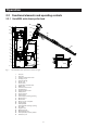
Operation 2.2 Functional elements and operating controls 2.2.1 VarioWIN with direct pellet feed 23 13 22 12 21 11 24 20 10 9 26 8 14 7 6 25 15 5 16 4 17 3 18 2 19 * 1 Fig.
Operation 2.2.
Operation 2.3 Opening the cladding door Warning of hot surface: risk of burns! Before touching the combustion chamber and ash door handles, you must switch off the boiler and let it cool. Insert the key, turn a quarter turn to the left and open the cladding door – Fig. 6. Fig. 6 2.4 Opening the cladding door with the key. Check before initial start-up a) System pressure (heating water pressure): The system must be filled and vented. With the system cold, pressure should be at least 1.
Operation 2.5 Filling the reserve supply container 2.5.1 VarioWIN Exklusiv-S – Manual filling Fold open the cover of the reserve supply container (Fig. 8) and fill the reserve supply container up to max. 1 cm below the edge. Close the cover. Tip:The reserve supply container should always be completely filled with pellets. This allows the incoming pellets to drop into the container better, reduces the size of the conical part of the pile and means that the container empties better.
Operation 2.6 InfoWIN The InfoWIN is the boiler’s display and operating unit. The InfoWIN unit consists of a large text display, an ON/OFF button with an LED signal lamp indicating Operation (green) or Malfunction (red); a switch for the flue cleaning function and four individual menu buttons. The function of each menu button is displayed on the Menu line.
Operation 2.7 Operating modes 2.7.1 OFF mode The boiler is switched off when in OFF mode. The display and all buttons, with the exception of the ON/OFF button, do not function. The LED on the InfoWIN is not illuminated – Fig. 10. 5s RESET Fig. 10 OFF mode 2.7.2 ON mode, lighting ON, self-test, lighting OFF Self-test active Press the ON/OFF button, lighting and display are switched on and the self-test starts automatically – Fig. 11. 5s .....
Operation 2.7.3 Pellet feed Pellet feed – Burnout Pellet feed Pellet feed from the storage room into the reserve supply container has been requested. Combustion is stopped. Pellet transport into the burner pot is stopped, the vacuum fan continues to run until all the remaining pellets have been burned and the burner pot has cooled down – Fig. 14. 42 °C Fig. 14 Burnout Info Menu Pellet feed in operation Pellet feed in operation The pellet feed is in operation.
Operation 2.7.5 Manual operation Note: Manual operation cannot be started in „solid fuel/buffer mode“. Manual operation must not be started if an installed solid fuel boiler is operating (heated up). Manual operation may be started if there is no solid fuel boiler installed or if this is not operating and only the buffer tank is active. In this case, first set the operating mode switch on the WVF module to relay test 2 or on the BUL module to relay test 1 (see WVF or BUL module operating manual).
Operation 2.7.6 Flue cleaning function This function aids the performance of legally-required emissions testing. Note: The flue cleaning function cannot be started in „solid fuel/buffer mode“.The flue cleaning function must not be started if an installed solid fuel boiler is operating (heated up). The flue cleaning function may be started if there is no solid fuel boiler installed or if this is not operating and only the buffer tank is active.
Operation 2.8 Operating phases 2.8.1 Standby Boiler temperature During this operating phase, the control system does not transmit requests for heat. The burner is switched off and the boiler temperature setpoint is 0 °C – Fig. 26. 42 °C Fig. 26 Standby Info Menu After an hour in standby mode, the display is shut down fully and only the green LED is lit up. The display is switched back on by pressing a button or when there is a heating requirement. 2.8.
Operation 2.9 Information text Boiler temperature 42 °C Pressing the Info button calls up the most important VarioWIN information – Fig. 33. 5s (Operating phases) Info Menu The arrow buttons select and display sub-menus – Fig. 34. By pressing the Back button (Fig. 35) or waiting 45 seconds, the screen returns to the standard display. RESET Fig.
Operation 2.9.3 Pellet consumption total Pellet consumption total The total amount of pellets consumed is displayed in tonnes – Fig. 38. Note: The „Pellet consumption total“ is a calculated value and can differ from the actual value by ±15%. 1.30 Fig. 38 t Back 2.9.4 Flue gas temperature Flue gas temperature If a flue gas temperature sensor (accessory) is connected, this function displays the current flue gas temperature – Fig. 39. The flue gas temperature is measured directly on the flue outlet.
Operation 2.10 Menu guide Boiler temperature 42 °C Pressing the Menu button changes the menu display to operator level or service level – Fig. 45. 5s (Operating phases) Info Menu Use the arrow buttons to select the operator level or service level (Fig. 46) and confirm with the Choose button – Fig. 47. The menu item or sub-menu item is exited by pressing the Back button (Fig. 48) or after a delay of 45 seconds. RESET Fig.
Operation Menu structure: Menu Service level Operator level Boiler cleaning Time With enable time (reserved for trained service personnel only) Feed operating mode1) With start time Automatic 1) Time profile feed1) Probe switching1) With enable time: Start/finish With start time: Start Without time control Switched off Only probe 1 Only probe 2 Time profile ash com.
Operation 2.10.1 Operator level Boiler temperature Pressing the Menu button changes to the „Operator level“ and „Service level“ – Fig. 49. 42 °C 5s (Operating phases) Info Menu RESET Fig. 49 Use the arrow buttons to select „Operator level“ and confirm with the Choose button – Fig. 50. Operator level Service level 5s Choose Back RESET Fig. 50 On the operator level, use the arrow buttons to select the required sub-menu (Fig. 51) and confirm with the Choose button.
Operation 2.10.1.1 Boiler cleaning Resetting the cleaning request Boiler temperature 42 °C After boiler cleaning has been performed (section 3.1), boiler cleaning must be confirmed so that the operating time until the next boiler cleaning is restarted. 5s (Operating phases) Lighting ON Boiler cleaning must not be reset if cleaning has not been carried out. RESET Pressing one of the six buttons switches the lighting and display on – Fig. 53. Fig. 53 Press the Menu button – Fig. 54.
Operation Pressing the Yes button resets the boiler cleaning – Fig. 58. The display shows „Parameter is saved“ for a few seconds (Fig. 59) and then changes back to the previous level – Fig. 60. Has boiler and burner cleaning been performed? 5s – Confirm Yes Back + RESET Fig. 58 Parameter is saved ..... 5s (Animated symbol) RESET Fig. 59 The menu item or sub-menu item is exited by pressing the Back button (Fig. 60) or after a delay of 45 seconds.
Operation 2.10.1.2 Time Boiler temperature This time is used for the time control of the pellet feed, automatic heating surface cleaning and automatic ash compression. 42 °C If the VarioWIN is operated with an MES control, the time is automatically adopted from the module and the time set here is overwritten. (Operating phases) Lighting ON If the VarioWIN is operated with REG standard control, the time must be set here too. Pressing one of the six buttons switches the lighting and display on – Fig.
Operation Save the changed time by pressing the Yes button – Fig. 66. The display shows „Parameter is saved“ for a few seconds (Fig. 67) and then changes back to the previous level – Fig. 68. Set time 13:50 – Save Yes No 5s + RESET Fig. 66 Parameter is saved 5s ..... (Animated symbol) RESET Fig. 67 The menu item or sub-menu item is exited by pressing the Back button (Fig. 68) or after a delay of 45 seconds.
Operation 2.10.1.3 Feed operating mode1) Boiler temperature This menu item sets: 42 °C – whether the feed is switched off, or – whether the feed should fill the pellet boiler with or without time control. 5s (Operating phases) Lighting ON Pressing one of the six buttons switches the lighting and display on – Fig. 69. RESET Fig. 69 Press the Menu button – Fig. 70. Boiler temperature 42 °C 5s (Operating phases) Info Menu RESET Fig.
Operation The factory setting for „Feed operating mode“ is „switched off“. Feed operating mode with enable time with start time without time control switched off Save Yes No Without time control: Select this if the feed noise (suction turbine) is not audible or intrusive in the living area (or adjacent premises). This mode guarantees the fewest possible feeds because the reserve supply container is always „run to empty“.
Operation 2.10.1.4 Time profile feed1) Boiler temperature The „Time profile feed“ menu item displays the corresponding setting option depending on the setting in the „Feed operating mode“ menu item (see section 2.10.1.3). 42 °C 5s (Operating phases) Lighting ON Setting: „with enable time“ see page 32 Setting: „with start time“ see page 31 Setting: „without time control“ or „switched off“ see page 33 RESET Pressing one of the six buttons switches the lighting and display on – Fig. 78. Fig.
Operation „with start time“ Feed start time A time can be set here in the „Time profile feed“ menu item for filling the reserve supply container if the „with start time“ setting is active in the „Feed operating mode“ menu item (see section 2.10.1.3). The reserve supply container is filled every day at the set time. Interim fills are also performed if the filling amount is not sufficient for 24 hours.
Operation „with enable time“ Feed enable time Start End The start and end of the enable time can be set here in the „Time profile feed“ menu item if the „with enable time“ setting is active in the „Feed operating mode“ menu item (see section 2.10.1.3). Factory setting „Feed enable time“: Choose Start 07:00 End 22:00 07:00 22:00 5s Back RESET Use the arrow buttons to select the time you want to change, „Start“ or „End“ – Fig. 87. Fig.
Operation The menu item or sub-menu item is exited by pressing the Back button (Fig. 92) or after a delay of 45 seconds. Feed enable time Start End Choose 07:00 22:00 5s Back RESET Fig. 92 The menu item or sub-menu item is exited by pressing the Back button (Fig. 93) or after a delay of 45 seconds. Boiler cleaning Time Feed operating mode Time profile feed Probe switching Time profile ash comp. Choose Back 5s RESET Fig.
Operation 2.10.1.5 Probe switching1) Boiler temperature If the VarioWIN is equipped with a pneumatic feed (suction system) with 2 or 3 probes, it is possible to set here which probe is used for sucking pellets from the pellet storage room. There are four different setting options: – – – – Automatic: Removal from Only probe 1: Removal from Only probe 2: Removal from Only probe 3: Removal from 42 °C (Operating phases) Lighting ON all 3 probes, automatic switching.
Operation Use the arrow buttons to select the required probe switching – Fig. 100. Probe switching Automatic Only probe 1 Only probe 2 Only probe 3 Save Yes No 5s RESET Fig. 100 Save the changed probe switching by pressing the Yes button – Fig. 101. The display shows „Parameter is saved“ for a few seconds (Fig. 102) and then changes back to the previous level.
Operation 2.10.1.6 Time profile ash compression (Exklusiv version only) Boiler temperature The ash in the ash pan is only compressed at the 2 set start times and when approx. 15 kg of fuel has been consumed. The start times can be set in steps of 15 minutes (start time 1 and start time 2). Factory setting: Start time 1: Start time 2: 42 °C 5s (Operating phases) Lighting ON 08:00 22:00 Pressing one of the six buttons switches the lighting and display on – Fig. 104. RESET Fig.
Operation Use the arrow buttons to select the start time you want to change, 1 or 2 – Fig. 109. Start times for ash compression Start time 1 08:00 Start time 2 22:00 Confirm the selected start time by pressing the Choose button – Fig. 110. Choose 5s Back RESET Fig. 109 Start times for ash compression Start time 1 08:00 Start time 2 22:00 Choose 5s Back RESET Fig. 110 Pressing the + or – button changes the time in 15 min. steps – Fig. 111.
Operation 2.10.2 Service level Operator level Service level System parameters, start-up and the actuator test can be displayed, performed and/or modified in the service level. 5s Choose Changes in the service level may be performed only by trained service personnel (for setting instructions, see the VarioWIN „Assembly instructions“). Back RESET Fig. 114 Service level only for trained service personnel 5s 5 s RESET Fig.
Operation 2.11 Heating system operation 2.11.1 VarioWIN with MES system control Switching on – Automatic operation: 1. Press the ON/OFF button on the InfoWIN panel, the display lighting is switched on, the signal lamp lights up green and a self-test is performed (see also section 2.7.2). After a successful self-test and if a setpoint is transferred by the control system, the VarioWIN automatically starts operation. 2. Set the operating mode switch(es) on the MES control module(s) to „Automatic operation“ .
Operation 2.10.2 VarioWIN with REG standard control Switching on – Automatic operation: 1. Press the ON/OFF button on the InfoWIN panel, the display lighting is switched on, the signal lamp lights up green and a self-test is performed (see also section 2.7.2). After a successful self-test and if a setpoint is transferred by the control system, the VarioWIN automatically starts operation. 2. Set both manual switches to the “Automatic” position. 3.
Operation How to switch to emergency (manual) operation Heating emergency operation: 1. There must be power to the boiler. The unit is switched on (otherwise, press the ON/OFF button InfoWIN unit). 2. Select “Manual operation” on the on the InfoWIN unit – see section 2.7.5. 3. Set the manual switch to the „Heating manual operation” position. 4. Also set the motorised mixing valve to manual operation and select the desired flow temperature.
Care, cleaning and maintenance 3.1 Care of cladding and keyboard foil Clean the cladding and the keyboard foil with a damp cloth as needed. In the event of heavy soiling, use soapy water or diluted suds (do not use strong cleaners or sharp cleaning instruments). 3.2 Cleaning and operating implements Install the hanger with the instructions folder, cleaning and operating implements, dowels and bolts on a wall in the boiler room / installation room – Fig. 122. 1 1 . . . . .
Care, cleaning and maintenance Care, cleaning and ash removal intervals Depending on pellet consumption Approx.
Care, cleaning and maintenance 3.4 Heating surfaces VarioWIN Premium Optimum efficiency is achieved when the heating surfaces are cleaned as often as possible using the key. However, no later than before the ash pan is emptied or ash is removed from the heating surfaces, the key should be connected on the right-hand side and moved back and forth several times – Fig. 123. Fig.
Care, cleaning and maintenance 3.6 Combustion chamber The VarioWIN is equipped with a cleaning interval display. The cleaning request for the combustion chamber and burner pot is displayed and must be reset after cleaning is finished – see section 2.10.1.1. „Boiler cleaning - Resetting the cleaning request“. Do not open the combustion chamber door during operation. Always switch the boiler off first with the ON/OFF button (Fig. 126) and wait until burnout mode has finished.
Care, cleaning and maintenance 3.6.2 Burner pot Do not open the combustion chamber door during operation. Always switch the boiler off first with the ON/OFF button and wait until burnout mode has finished. It is essential to let the boiler cool down before cleaning.
Care, cleaning and maintenance 3.7 VarioWIN reserve supply container It is necessary to clean the reserve supply container if too much dust has collected on the sides or at the opening above the auger, or there are foreign bodies in the reserve supply container. In order to be able to check this, there must not be any pellets in the reserve supply container.
Care, cleaning and maintenance VarioWIN Exklusiv with pneumatic feed (suction system): – Switch off the VarioWIN with the ON/OFF button on the InfoWIN (Fig. 133) and wait until the display has gone out. – Open the cover of the reserve supply container – Fig. 134. Fig. 133 Fig. 134 Switching off the VarioWIN Folding open the cover – Remove both knurled screws (Fig. 135) and fold open the inspection cover (Fig. 136).
Care, cleaning and maintenance 3.8 Top heating surfaces and linkage These parts are automatically checked and cleaned as part of the annual maintenance by WINDHAGER Customer Service or the customer service PARTNER. Always switch the boiler off first with the ON/OFF button (Fig. 139) and wait until burnout mode has finished. It is essential to let the boiler cool down before cleaning. – Remove the front cover – Fig. 140. Fig. 139 Switching off the VarioWIN Fig.
Care, cleaning and maintenance 3.9 Blower wheel, blower box, exhaust pipe and rotary feeder These parts are automatically checked and cleaned as part of the annual maintenance by WINDHAGER Customer Service or the customer service PARTNER. It is essential to let the boiler cool down before cleaning. – Unhook the rear right side panel cladding and disconnect the mains power plug over the control panel – Fig. 146 – Remove the screw under the mains power plug on the control panel (Fig.
Care, cleaning and maintenance Assembly: – Guide the blower unit in at the back using the stay bolts and attach at the front with two wing nuts. – Reconnect the blower plug. 3.9.1 Rotary feeder VarioWIN S/P with 41 kg reserve supply container / pneumatic pellet feed: Cleaning: – Unscrew the screw plug (WAF 22) from the rotary feeder (Fig. 151) and vacuum pellet dust out of the rotary feeder using a vacuum cleaner. Screw plug Fig.
Troubleshooting The VarioWIN pellet boiler is self-monitoring during operation. All deviations from normal operation are displayed on the InfoWIN by information, fault or alarm messages. If one of these messages appears, the LED lights up red, an information, fault or alarm symbol flashes, and an information code is displayed along with a brief description in full text – Fig. 154. Pressing the Info button (Fig. 154) displays the related information text (Fig. 155).
Troubleshooting 4.1 No display on InfoWIN Code Meaning/effect Cause/remedy a) No electricity, check the cable to the device and the building fuse. No display – 4.2 Boiler is off, cannot be switched on with the ON/OFF button. b) No electricity, device fuse defective – check and replace if necessary – see page 56, Fig. 160.
Troubleshooting 4.3 Fault messages Code Meaning/effect Cause/remedy No pellet feed is possible. The boiler does not operate. a) No pellets at the suction probe – Set „probe switching“ to „automatic“ or select another probe (see section 2.10.1.5). Press the Reset button Feed is not sucking any pellets in b) Feed hose blocked at the cyclone intake or entry to the changeover unit – FE 238 Check pellet supply in storage room and feed hose. Press Reset. clear it. Press the Reset button.
Troubleshooting 4.4 Alarm messages Code Meaning/effect Cause/remedy Shake-out motor no longer moves or no longer reaches the end position, boiler switches to burnout mode. a) Burner contamination; close combustion chamber doors, press reset button; once the alarm message is rectified, clean the burner pot as described in section 3.6.
Troubleshooting Code Meaning/effect Cause/remedy The boiler switches to burnout mode. Boiler sensor defective AL 076 Check the boiler sensor and connections. Press Reset. a) Press the Reset button. If the malfunction recurs immediately after a short period, or recurs at regular intervals, contact Windhager Customer Service or your heating technician. b) Renew the boiler sensor, inform Windhager Customer Service or a heating technician. The boiler switches to burnout mode.
Troubleshooting Code Meaning/effect Cause/remedy a) VarioWIN D without feed or with direct pellet feed: The reserve supply container is empty. Fill fuel into the reserve supply or year-round pellet container (see section 2.5). Press the Reset button until the boiler starts operating again. The alarm message AL 171 may light up again on up to 2 occasions, press the Reset button. b) Clean the burner pot (see section 3.6), empty the ash pan, press the Reset button.
Declaration of conformity for the VarioWIN pellet boiler series Issued by: WINDHAGER ZENTRALHEIZUNG Technik GmbH Anton-Windhager-Strasse 20 A-5201 Seekirchen Subject of the declaration: VarioWIN pellet boiler series The appliances comply with the requirements in the following documents: Document no. Title 2006/42 EC Machinery Directive 2004/108 EC EMC Directive 89/106 EEC Construction Products Directive Standard EN 14785 EN 60335-1 EN 61000-6-1 EN 61000-6-3 Seekirchen, 16. 2.
Guarantee and warranty limitations The guarantee and warranty limitations require that the boiler and related accessories be properly installed and started up by WINDHAGER Customer Service or Customer Service PARTNER; otherwise the manufacturer’s guarantee will not be honoured. Malfunctions resulting from improper operation or adjustment as well as use of poor or not recommended fuel types are not covered by the guarantee and warranty.