Table of Contents Do This First ................................................................................................................. 3 For Windows 95 Installation ................................................................................. 3 For Windows NT 4.0 Installation .......................................................................... 5 Installing the Modem ...................................................................................................
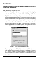
Do This First Please read the following tips carefully before attempting to install your new modem. For WINDOWS 95 INSTALLATION If you are replacing the modem in your computer system with this modem, be sure to remove all other modem drivers. Go to: Start-Settings-Control Panel and double-click on the System icon. Select the Device Manager tab. Doubleclick on the Modems icon in the device tree to show the modems installed.
To find the Windows 95 Version on your system, select: Start-Settings-Control Panel. Double-click on the System icon. If the version of Windows 95 is 4.00.950 or 4.00.950A, go to: Start-Programs and select Windows Explorer. Go to the UNIMODEM directory of the CD-ROM (the UNIMODEM driver is sometimes supplied on a separate floppy) that came with your modem and right-click on UNIMODV.INF (or UNIMODV, whichever is displayed) then click on Install. Restart your computer to enable the drivers.
Do not reassign an interrupt that is already in use by an ISA card to the PCI bus. Since each BIOS manufacturer has a different way of handling these configurations, you may have to use trial-and-error to get your modem properly configured. Be sure to Save the settings before exiting the BIOS Setup. You are now ready to install the modem. Proceed to the Installing the Modem section. For WINDOWS NT 4.
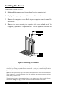
Installing The Modem HARDWARE INSTALLATION 1. Switch off the computer and all peripheral devices connected to it. 2. Unplug the computer power cord from the wall receptacle. 3. Remove the computers cover. Refer to your computer owners manual for instructions. 4. Remove the screw securing the expansion slot cover behind one of the computers available PCI expansion slots. Lift the expansion slot cover out as shown below.
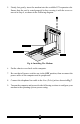
5. Firmly, but gently, insert the modem into the available PCI expansion slot. Ensure that the card is seated properly before securing it with the screw removed in Step 4, as shown in the following diagram: Fig. 6: Installing The Modem 6. Put the chassis cover back on the computer. 7. Be sure that all power switches are in the OFF position, then reconnect the power cables to the computer and its peripherals. 8. Connect the telephone line cable to the Line (Telco) jack as shown in Fig.7. 9.
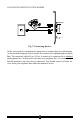
CONNECTING DEVICES TO THE MODEM Fig.7: Connecting Devices On the rear panel of your modem are input jacks to connect devices to the modem. As shown in the diagram, there are jacks for connection to a phone and to a phone line. The connector labeled Line (Telco) is meant to be connected to a standard analog phone line. To help reduce the load on your phone line, it is recommended that the modem be the only device connected.
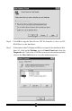
CONFIGURING WINDOWS 95 Step 1 Upon startup, Windows 95 detects the modem and displays the New Hardware Found dialog box. Select Driver from disk provided by hardware manufacturer then Click OK. Step 2 If Windows asks for an installation disk, click OK and type A:\ in the dialog box that appears and click OK. Step 3 After the installer has copied the .INF files to the hard disk, a New Hardware Found dialog box should appear prompting for the Wave Device for Voice Modem. Click OK.
Step 4 Click OK to copy the Wave Device .INF file from the A:\ drive (or CDROM Drive) to the hard drive. Step 5 To determine what COM port and IRQ is assigned to the modem in Windows 95, click on the Modems icon in Control Panel and select the Diagnostic tab. Click on the COM Port icon next to the modem and then click on the More Info button to view the modem properties.
CONFIGURING WINDOWS 95 OEM SR2 Step 1 Upon startup, Windows 95 detects the modem and launches the Update Device Driver Wizard dialog box. Insert the diskette containing the modems Windows 95 .INF files and click Next >. Step 2 After Windows 95 has found the updated drivers for your modem, click Finish. Step 3 If Windows asks for an installation disk, click OK and type A:\ in the dialog box that appears and click OK.
Step 4 After the Wizard has copied the .INF files to the hard disk, it should detect Wave Device for Voice Modem and prompt for its driver. Click Next>. Step 5 Click Finish to copy the Wave Device .INF file from the A:\ drive (or CD-ROM Drive) to the hard drive. Step 6 To determine what COM port and IRQ is assigned to the modem in Windows 95, click on the Modems icon in Control Panel and select the Diagnostics tab.
Step 7 Remember this COM port number. When you install your Data/Fax software or internet browser program, you may need to set your modem port location to this same number.
CONFIGURING WINDOWS NT 4.00 In order to install the modem in Windows NT, you must prepare the installation utility supplied on a separate floppy diskette. This diskette should be labeled Windows NT Installation Utility. This program will allow for easy installation and uninstallation of your PCI Windows Modem. Step 1 Install your modem into an available PCI slot (see the Do This First section for important preinstallation information).
Step 7 After the installation utility has finished installing the drivers, restart your computer to enable the drivers. Step 8 Click on the Modems icon in the Control Panel. Verify that Windows NT has correctly found the modem. Step 9 If you wish to use your modem to dial into a Windows NT Remote Access Server or wish to connect to the Internet, you will need to configure Dial-up Networking. Go to: Start-Settings-Control Panel and doubleclick the Network icon.
NT may ask for its own disks or CD-ROM for some files. Insert as required. After you have installed Remote Access Service add the appropriate protocols as directed (i.e.. TCP/IP for Internet Access). Step 10 At the Remote Access Setup dialog box, click on Add RAS Device you wish to add and Click OK. . Select the Step 11 Click Continue to finish the Installation. Step 12 After Windows NT has completed the binding process, allow Windows NT to shut down and restart the computer.
Installing and Configuring Communications Software If your modem came with a communications software package, it is strongly recommended that you use this software for your modem. Its default installation parameters have been specially configured to work with this modem. The Users Guide for this program can be found inside the modem package. It can be supplied in either soft-bound copy or on CD-ROM (depending on the model you purchased). Some configurations are packaged without communications software.
Using the Modems Voice Features This modem supports TIA IS-101 commands applicable to a Telephone Answering Device. In order to take advantage of this feature, you will need a Sound Blaster® compatible sound card equipped with an external microphone and external speakers. A software application; such as the one supplied with the modem; which supports these TAD functions is also required.
Troubleshooting This section lists some common problems and offers suggestions for a solution. It is important to remember that this modem is a Windows 95/NT based modem and requires 32bit virtual device drivers. It therefore cannot work in Windows 3.1 which cannot use these drivers. The modem also cannot work in DOS regardless of version. It is a software installed device and has no provisions for manual configuration.
STEP 2: Check Modem Properties. From the Device Manager tab within System Properties, double-click the Modems icon in the device tree to show what modems are installed. Highlight your modem by clicking once on the icon and then click the Properties button. Read the Device Status under the General tab to see if the device is working properly.
If you receive an error message or the panel is blank, go to the Does Not Install section. STEP 4: Does Not Install. The most likely reason for a non-installation in Windows 95 is a lack of IRQ resources. The modem needs one IRQ and two I/O addressees in order to function. Modern computer systems are usually equipped with soundcard, CD-ROM drive, Hard-drive, floppy drive, video card, two COM Ports, one LPT port, keyboard, and a mouse.
Certain full-featured sound cards require three IRQs to support all their functions. When one becomes available, they take it. This situation requires that you remove your sound card, free an interrupt, install the modem and verify its operation, and then reinstall the sound card. This procedure may also work for sound cards that have lost their sound after the modem has been installed or if the modem will not install in a system with a sound card.
If you cannot find a particular file, it usually means it was not installed. After all instances of these files have been deleted, restart your system. Windows 95 and 95a users see below. If you are using Windows 95 OEM SR2 (see the Do This First section for Windows 95 for instructions on how to determine your Windows 95 version), you need only delete the files listed.
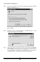
When a file is found, it will have the name oem#.inf. Delete only an oem inf file. To delete a file, highlight the file name by clicking once and then select File-Delete from the File menu. After the file is deleted, you now need to find the other inf file. Go to the Advanced tab and type the following in the Containing text field: V.90_PCI_Windows_Modem as shown below. After Windows finds the other file, delete it as before.
Common Problems: No Dialtone Error Make sure you have connected the phone cable into the right connector on the back of the modem. See Figure 7: Connecting Devices. You may have too many devices connected to the phone line. Remove all other equipment. Your modem may not recognize overseas dialtone. Use ATX0 to have the modem ignore (not look for) the dialtone before dialing.
You may have other telephone devices connected to the phone line. To help your modem achieve the best connection possible, remove all extra devices connected to the telephone line when the modem is in use. This includes extension phones, answering machines, cordless phone bases, caller ID boxes, etc. Dont just disconnect the phone cable from the units. Disconnect the phone cable from the wall. This reduces the load on your phone line and keeps signal attenuation to a minimum.
hear a hissing or humming sound in the background? Is there popping or crackling during your call? These are phone line problems. In the case of distortion, your phone line is bad. Humming may be due to the cabling inside your residence coming too close to a high current appliance or you may have a cordless phone recharger base connected to the phone line. Popping or crackling usually indicates a loose connection to the outside line or water dripping on the hookup outside your house.
Appendix A: AT Command Set AT Commands AT commands are issued to the modem to control the modems operation and software configuration. AT commands can only be entered while the modem is in command mode. The format for entering AT commands is: TYPE: ATXn where X is the AT command, and n is the specific value for that command. PRESS: Enter Any command issued is acknowledged with a response in text format known as result codes.
Bn Communication Standard Setting This command determines CCITT vs. Bell standard. B0: B1: B2: B3: B15: B16: Selects CCITT V.22 mode when the modem is at 1200 bits/s. Selects Bell 212A when the modem is at 1200 bits/s (default). Unselects V23 reverse channel ( same as B3). Unselects V23 reverse channel ( same as B2). Selects V.21 when the modem is at 300 bits/s. Selects Bell 103J when the modem is at 300 bits/s (default).
L Redials last number. Should be the first character following ATD, ignored otherwise. The modem displays the dialing string in the following format: Dialing xxxxxxx where xxxxxxx is the last number dialed. P Pulse dialing. (e.g. ATDPxxx. Dialing set to pulse as default.) T Touch-tone dialing (default). (e.g. ATDTxxx. Dialing set to tone as default.) , Pause during dialing. Pause for time specified in Register S8 before processing the next character in the dial string. W Wait for dial tone.
Result Codes: OK ERROR n=1 Otherwise Hn Hook Control This command instructs the modem to go on-hook to disconnect a call, or offhook to make the phone line busy. H0: H1: Modem goes on-hook (default). Modem goes off-hook. Result Codes: OK ERROR n = 0, 1 Otherwise In Request ID Information This command displays specific product information about the modem. I0: I1: I2: I3: I4: I5: I6 I7 I8 I9: Returns default speed and controller firmware version.
L0: L1: L2: L3: Selects lowest volume. Selects low volume. Selects medium volume (default). Selects high volume. Result Codes: OK ERROR n = 0, 1, 2, 3 Otherwise Mn Monitor Speaker Mode This command turns the speaker on or off. M0: M1: M2: M3: The speaker is off. The speaker is on until the modem detects the carrier signal (default). The speaker is always on when modem is off-hook. The speaker is on until the carrier is detected, except while dialing.
O1: O3: mode (see AT Escape Sequence, +++). This command issues a retrain before returning to on-line data mode. This command issues a rate renegotiation before returning to online data mode. Result Codes: OK ERROR n = 0, 1, 3 Otherwise P Select Pulse Dialing This command configures the modem for pulse (non-touch-tone) dialing. Dialed digits are pulsed until a T command or dial modifier is received. Tone dial is the default setting.
Result Codes: OK ERROR n = 0, 1 Otherwise Wn Result Code Option W0: W1: W2: CONNECT result code reports DTE speed. Disable protocol result codes. CONNECT result code reports DTE speed. Enable protocol result codes. CONNECT result code reports DCE speed. Enable protocol result codes (default). Result Codes: OK ERROR n = 0, 1, 2 Otherwise Xn Result Code Selection and Call Progress Monitoring This command enables tone detection options used in the dialing process.
Busy Tone Detect Disabled: The modem ignores any busy tones it receives. Enabled: The modem monitors for busy tones. Ext. X0 X1 X2 X3 X4 X5 X6 X7 Result Code Disable Enable Enable Enable Enable Enable Enable Disable Dial Tone Detect Disable Disable Enable Disable Enable Enable Enable Enable Busy Tone Detect Disable Disable Disable Enable Enable (default) Enable Enable Enable Result Codes: OK ERROR Yn n = 0, 1, 2, 3, 4, 5, 6, 7 Otherwise Long Space Disconnect Long space disconnect is always disabled.
&Bn V.32 Auto Retrain This modem always auto retrains. &B0: Disable V.32 auto retrain. ( NOT SUPPORTED) &B1: Enable V.32 auto retrain (default). Result Codes: OK ERROR &Cn n=1 Otherwise Data Carrier Detect (DCD) Control Data Carrier Detect is a signal from the modem to your computer indicating that the carrier signal is being received from a remote modem. DCD normally turns off when the modem no longer detects the carrier signal. &C0: The state of the carrier from the remote modem is ignored.
&D3: Monitor DTR signal when an on-to-off transition occurs, the modem performs a soft reset as if the ATZ command was received. Result Codes: OK ERROR &Fn n = 0, 1, 2, 3 Otherwise Load Factory Settings This command loads the configuration stored and programmed at the factory. This operation replaces all of the command options and the S-register settings in the active configuration with factory values. &F0: Recall factory setting as active configuration. (default) &Gn V.
&Kn Local Flow Control Selection &K0: Disable flow control. &K1: Reserved. &K2: Reserved. &K3: Enable RTS/CTS flow control (default). &K4: Enable XON/XOFF flow control. Result Codes: OK ERROR &Mn n = 0, 3, 4 Otherwise Asynchronous Communications Mode &M0: Asynchronous mode (default). &M1: Reserved. &M2: Reserved. &M3: Reserved. &M4: Reserved. Result Codes: OK ERROR &Pn n=0 Otherwise Pulse Dial Make-to-Break Ratio Selection This Command is effective only for Japan.
&Q3: Reserved. &Q4: Reserved. &Q5: Error Control Mode, buffered (default). Same as \N3. &Q6: Asynchronous Mode, buffered. Same as \N0. &Q7: Reserved. &Q8: MNP error control mode. If an MNP error control protocol is not established, the modem will fallback according to the current user setting inS36. &Q9: V.42 or MNP error control mode. If neither error control protocol is established, the modem will fallback according to the current user setting inS36.
BusyTone Detect LSD Action DTR Action Enable Standard RS232 Standard RS232 X &C &D Press any key to continue; ESC to quit. Option Selection AT Cmd V22b Guard Tone Flow Control Error Control Mode Data Compression AutoAnswerRing# AT Escape Char CarriageReturn Char Linefeed Char Backspace Char Blind Dial Pause NoAnswer Timeout , Pause Time Disable Hardware V42, MNP, Buffer V42bis/MNP5 0 43 13 10 8 2 sec 50 sec 2 sec &G &K \N %C S0 S2 S3 S4 S5 S6 S7 S8 Press any key to continue; ESC to quit.
&Wn Store Current Configuration This command stores certain command options and S-register values into the modems nonvolatile memory. The ATZ command or a powerup reset of the modem restores this profile. Result Codes: OK ERROR &Yn n=0 Otherwise Select Stored Profile for Hard Reset This command does not change the behavior of the modem but is included for compatibility with applications that issue the &Y0 command: &Y0: Select stored profile 0 on powerup &Y1: ERROR.
\A2 192 characters. \A3 256 characters (DEFAULT). Result Codes: OK ERROR \Bn n = 0, 1, 2, 3 Otherwise Transmit Break to Remote In non-error correction mode, the modem will transmit a break signal to the remote modem with a length in multiples of 100ms according to parameter specified. The command works in conjunction with the \K command. \B1-\B9 Break length in 100ms units. (Default = 3.) (Non-error corrected mode only.) Result Codes: OK NO CARRIER \G If connected in data modem mode.
\Kn Break Control Controls the response of the modem to a break received from the DTE or the remote modem or the \B command. The response is different in three separate states. The first state is where the modem receives a break from the DTE when the modem is operating in data transfer mode: \K0 Enter on-line command mode, no break sent to the remote modem. \K1 Clear data buffers and send break to remote modem. \K2 Same as 0. \K3 Send break to remote modem immediately. \K4 Same as 0.
sending or receiving data. \N0: Buffer mode. No error control (same as &Q6). \N1: Direct mode. \N2: MNP or disconnect mode. The modem attempts to connect in MNP 2-4 error control procedure. If this fails, the modem disconnects. This is also known as MNP reliable mode. \N3: V.42, MNP, or buffer (default). The modem attempts to connect in V.42 error control mode. If this fails, the modem attempts to connect in MNP mode. If this fails, the modem connects in buffer mode and continues operation.
before disconnecting when no data is sent or received. A setting of zero disables the timer. Alternatively, this timer may be specified in register S30. This function is only applicable to buffer mode.
-V90=x V.90 Downstream Rate and Control Use this command to enable/disable V.90 connection and to control V.90 connection rates. The command syntax is AT-V90=x. Where x is a value from the list below. AT-V90=x 0 1 2 3 4 5 6 7 8 9 10 11 12 13 14 15 16 17 18 19 20 21 Downstream Rate V.
%Cn Enable/Disable Data Compression Enables or disables data compression negotiation on an error corrected link. %C0 Disables data compression %C1 Enables both V.
AT Commands for Testing and Debugging The following commands are to be used for testing and debugging only and are not meant for general use. &Tn Self-Test Commands This command allows the user to perform diagnostic tests on the modem. These tests can help to isolate problems when experiencing periodic data loss or random errors. &T0: Abort. Stops any test in progress. &T1: Local analog loop. This test verifies modem operation, as well as the connection between the modem and computer.
ATI11 Display Diagnostic Information for the last modem connection The ATI11 command displays the following diagnostic information for the last modem connection. A value of NA will be displayed if that parameter is not applicable for that connection. Table 1. Diagnostic Information Description Example Last Connection V.34 V.90/56K/V.34/V.32 - The last data connection is successful. Failure The last data connection failed.
Description Example Comments Transmit Frame Error Count 10 Number of frame errors transmitted Receive Frame Count 5000 Number of HDLC frames received. Receive Frame Error Count 10 Number of frame errors received Retrain and Rate Negotiate Event 1 the local Modem Number of retrains initiated by the local modem. Retrain and Rate Negotiate Event 1 remote Modem Number of retrains initiated by the remote modem.
S-Registers Reference S-Registers Definitions S-registers generally affect how the AT commands perform. Contents of the registers can be displayed or modified when the modem is in command mode. To display the value of an S-register: TYPE: ATSn? where n is the register number. PRESS: Enter To modify the value of an S-register: TYPE: ATSn = r where n is the register number, and r is the new register value.
Range: Default: Units: 0−255 43 ASCII S3 Command Line Termination Character (user defined) This register determines the ASCII values as the carriage return character. This character is used to end command lines and result codes. Range: Default: Units: 0−127, ASCII decimal 13 (carriage return) ASCII S4 Response Formatting Character (user defined) This register determines the ASCII value used as the line feed character.
ever, may be affected by some ATX options according to country restrictions. Range: Default: Units: 2-65 2 seconds S7 Connection Completion Time-Out This register sets the time, in seconds, that the modem must wait before hanging up because carrier is not detected. The timer is started when the modem finishes dialing (originate), or goes off-hook (answer). In originate mode, the timer is reset upon detection of an answer tone if allowed by country restriction.
Range: Default: Units: 50-150 95 0.001 seconds S12 Escape Guard Time This register sets the value (in 20 ms increments) for the required pause after the escape sequence (default 1 s). Range: Default: Units: 0-255 50 0.02 seconds S14 General Bit Mapped Options Status Indicates the status of command options. Only bit 2 and bit 5 are used, read only.
Bits 4-6 result codes (Xn) 0 = X0 selected 4 = X1 selected 5 = X2 selected 6 = X3 selected 7 = X4 selected (Default) Bit 7 Pulse dial make/break ratio (&Pn) 0 = 33/67 make/break ratio (&P1, &P2) (Default) 1 = 39/61 make/break ratio (&P0) Default: 112 (01110000b) S24 Timer to Control Sleep Mode This command displays the number of seconds of inactivity (no characters sent from the DTE, no RING) in the off-line command state before the modem places itself into standby mode.
S32 Synthetic Ring Volume This register specifies a synthetic ring volume in dB with an implied minus sign. Range: Default: 16 S33 Synthetic Ring Frequency This register specifies a synthetic ring frequency. Valid ranges are 0-5, with 0= disabled and 1-5 corresponding to 5 ring frequencies. Range: 0-5 Default: 0 S35 Data Calling Tone Data Calling Tone is a tone of certain frequency and cadence as specified in V.25 which allows remote Data/FAX/Voice discrimination.
S37 = 4 S37 = 5 S37 = 6 S37 = 7 S37 = 8 S37 = 9 S37 = 10 S37 = 11 S37 = 12 S37 = 13 S37 = 14 S37 = 15 S37 = 16 S37 = 17 S37 = 18 S37 = 19 reserved 1200 bits/s 2400 bits/s 4800 bits/s 7200 bits/s 9600 bits/s 12000 bits/s 14400 bits/s 16800 bits/s 19200 bits/s 21600 bits/s 24000 bits/s 26400 bits/s 28800 bits/s 31200 bits/s 33600 bits/s S38 56K Dial Line Rate (default 1) There are 2 S-registers which support K56flex connections.
S20=2 Startup at initial rate of 9600 or below. Range: Default: 0-2 0 S42 Auto Rate (default 1, range 0-1) This command is used for testing and debugging only. V.32bis and V.22bis auto rate is disabled. Retrain operation is disabled or enabled in data mode, and fallback is disabled in data mode. 0 = auto rate disabled, 1 = enabled. Range: Default: 0-1 1 S43 Auto Mode (default 1, range 0-1) This command is used for testing and debugging only. V.32bis startup auto mode operation disabled.
S89 Timer to Control Sleep Mode This command displays the number of seconds of inactivity (no characters sent from the DTE, no RING) in the off-line command state before the modem places itself into standby mode. A value of zero prevents standby mode. Note: If a number between 1 and 4 is entered for this register, it will set the value to 5, and the inactivity before standby will be 5 seconds. This is done for compatibility with previous products which allowed time-outs down to 1 s.
Table 2.
CONNECT CONNECT CONNECT CONNECT CONNECT CONNECT CONNECT CONNECT CONNECT CONNECT CONNECT CONNECT CONNECT CONNECT CONNECT CONNECT 33333 34666 36000 37333 38666 40000 41333 42666 44000 45333 46666 48000 49333 50666 52000 53333 EC* EC* EC* EC* EC* EC* EC* EC* EC* EC* EC* EC* EC* EC* EC* EC* Connection Connection Connection Connection Connection Connection Connection Connection Connection Connection Connection Connection Connection Connection Connection Connection at at at at at at at at at at at at at at at
Appendix B: Communications Regulations FCC REGULATIONS The following statements are provided in accordance with the Federal Communications Commission (FCC) regulations. Please read these statements carefully before installing your modem. FCC PART 68 REQUIREMENTS This equipment complies with Part 68 of the FCC Rules. On the bottom of this equipment is a label that contains, among other information, the FCC Registration Number and Ringer Equivalence Number (REN) for this equipment.
DECLARATION of CONFORMITY This equipment has been tested and found to comply with the limits for a Class B digital device, pursuant to Part 15 of the FCC Rules. These limits are designed to provide reasonable protection against harmful interference in a residential installation. This equipment generates, uses and can radiate radio frequency energy and, if not installed and used in accordance with the instructions, may cause harmful interference to radio communications.
CANADIAN DEPARTMENT OF COMMUNICATIONS (CDOC): Requirements for End Users: Notice: The Canadian Department of Communications label identifies certified equipment. This certification means the equipment meets certain telecommunications network requirements. The Department does not guarantee the equipment will operate to the users satisfaction. Before installing this equipment users should ensure that connection to the line is allowed by the local telecommunications company.