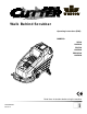
Walk Behind Scrubber Operating instructions (ENG) MODELS: SC326 10052220 SCC326 10052260 BSCSC326 10052890 IPX4 Read these instructions before using the machine.
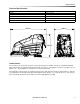
Machine Data Label Overview The Saber Cutter is a battery powered, self-propelled, hard floor scrubber intended for commercial use. The appliance applies a cleaning solution onto a hard floor, scrubs the floor with brushes or pads, and then vacuums the soiled water back into the recovery tank. Warranty Registration Thank you for purchasing a Windsor product. Warranty registration is quick and easy. Your registration will allow us to serve you better over the lifetime of the product.
Table of Contents Machine Data Label . . . . . . . . . . . . . . . . . . . . . . . . . . 2 Overview . . . . . . . . . . . . . . . . . . . . . . . . . . . . . . . . . . 2 Table of Contents . . . . . . . . . . . . . . . . . . . . . . . . . . . 3 How To Use This Manual . . . . . . . . . . . . . . . . . . . . . 4 Safety Important Safety Instructions . . . . . . . . . . . . . . . . . . 5 Hazard Intensity Level . . . . . . . . . . . . . . . . . . . . . . . 6 Safety Label Location . . . . . . . . . . . . . . . .
How To Use This Manual The SAFETY section contains important information regarding hazardous or unsafe practices of the machine. Levels of hazards are identified that could result in product damage, personal injury, or severe injury resulting in death. This manual contains the following sections: • • • • • How to Use This Manual Safety Operations Maintenance Parts List The OPERATIONS section is to familiarize the operator with the operation and function of the machine.
Safety Important Safety Instructions When using this machine, basic precaution must always be followed, including the following: READ ALL INSTRUCTIONS BEFORE USING THIS MACHINE. To reduce the risk of fire, electric shock, or injury: Use only indoors. Do not use outdoors or expose to rain. Use only as described in this manual. Use only manufacturer’s recommended components and attachments.
Safety The following symbols are used throughout this guide as indicated in their descriptions: Hazard Intensity Level There are three levels of hazard intensity identified by signal words -WARNING and CAUTION and FOR SAFETY. The level of hazard intensity is determined by the following definitions: WARNING - Hazards or unsafe practices which COULD result in severe personal injury or death. CAUTION - Hazards or unsafe practices which could result in minor personal injury or product or property damage.
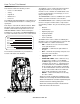
Safety Safety Label Location NOTE: These drawings indicate the location of safety labels on the machine. If at any time the labels become illegible, promptly replace them.
Operations Technical Specifications ITEM Nominal power Rated Voltage Rated Amperage Batteries Scrub Brush Motors Vacuum Motor Propelling Motor Mass (GVW) Weight empty without batteries Solution Control Solution tank capacity Recovery tank capacity Scrub brush diameter 32 in. (81 cm) scrub head Scrub brush pressure 130 lbs restricted (356n-578n) Scrub brush speed Tires Casters Foundation Pressure Maximum Speed Frame Construction Brakes (optional) Minimum aisle u-turn width with 32 in.
Operations Technical Specifications ITEM Height Length with 32 in. (81 cm) scrub head Width without squeegee and scrub head Width of squeegee for 32 in. (81 cm) scrub head Width of scrub path for 32 in. (81 cm) scrub head MEASURE 46 in (117 cm) 71 in (180) 28 in (71 cm) 39 in (99 cm) 32 in (81 cm) WIDTH LENGTH HEIGHT SPECIAL NOTES: The sound pressure level at the operator's ear was measured to be 75 dBA.
Operations How The Machine Works The Saber Cutter is a battery powered, self-propelled, hard floor scrubber intended for commercial use. The appliance applies a cleaning solution onto a hard floor, scrubs the floor with brushes, and then vacuums the soiled water back into the recovery tank. The machine's primary systems are the solution system, scrub system, recovery system, and directional control system. The function of the solution system is to store cleaning solution and deliver it to the scrub system.
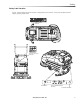
Operations Components 12 3 14 7 1 2 15 11 10 9 8 6 13 4 5 1. Control Panel 2. Front Cover 3. Recovery Tank 4. Recovery Tank Drain Hose 5. Scrub Head Shrouds 6. Solution Tank 7. Solution Tank Cover 8. Solution Tank Drain Hose 9. Solution Strainer 10. Squeegee 11. Aqua-Mizer 12. Top Cover 13. Vacuum Motor 14. Recovery Tank Dome 15.
Operations Controls 13 2 3 5 6 9 8 1 15 4 7 10 14 11 12 12 86039090 CUTTER 36V
Operations 1. Key Switch 4. PROPEL CONTROL LEVERS 2. Emergency Shut-Off Switch Controls the machine direction, and scrub brushes and solution flow. 3. Speed Control Knob To propel machine forward, squeeze either propel lever. 4. Propel Control Lever 5. Reverse Button The scrub brushes will not rotate and the solution will not flow to scrub deck with the propel levers in neutral. 6. Brush Switch 7. Brush Lift Lever 8. Solution Control Knobs 5. REVERSE BUTTON 9.
Operations 7. BRUSH PRESSURE LEVER 10. SQUEEGEE LIFT LEVER Adjusts the amount of brush pressure to the floor by raising or lowering the scrub deck. Raises and lowers the squeegee. To apply brush pressure, lower brush pressure lever to floating position. To apply additional pressure, place lever in restricted position. Lock the lever into the lower notch. Push the lever forward to move in a downward motion. Pull back on lever and release for floating position.
Operations 13. BATTERY CHARGE LEVEL INDICATOR Indicates the charge level of the batteries. The meter display is divided into 10 vertical bars. Bar illuminated on the far right indicate full charge. Bars flashing near the left side indicate the batteries should be recharged. Further operation of the machine could damage the machine or the batteries. When the machine is left overnight with less than a full charge, the display may initially indicate a full charge.
Operations Machine Operation Filling Solution Tank Pre-Run Machine Inspection Do a pre-run inspection to find possible problems that could cause poor performance or lost time from breakdown. Follow the same procedure each time to avoid missing steps. NOTE: See maintenance section for pre-run machine inspection checklist items. FOR SAFETY: Before leaving or servicing machine; stop on level surface, turn off machine and remove key. 1. Turn the machine power off. 2.
Operations Normal Scrubbing To Begin Scrubbing Plan the scrubbing pattern in advance. The longest track is around the perimeter of the area to be cleaned. For efficient operation, the runs should be the longest possible without turning, stopping, or raising and lowering scrub deck/squeegee. When operating the machine around people, pay close attention for unexpected movement. Use extra caution around children.
Operations Double Scrub Recovery Tank For floors which are heavily soiled or have thick accumulations of floor finish may not clean sufficiently with one pass. In these cases it will be necessary to double scrub. 1. Unhook the large drain hose from the retainer. Unscrew the T-handle on plug enough to loosen plug, then lower hose in direction of the drain. Do not stand in front of end of hose. Recovered solution will come out with force. Slowly remove plug from drain hose. 1.
Maintenance Service Schedule MAINTENANCE DAILY Check batteries after charging; add water if necessary Check pad wear to prevent buildup of chemicals Check linkages and connectors for wear and damage Check hoses for wear, blockages, or damage Clean squeegee; check for adjustment; inspect for wear Check handles, switches, knobs, domes, and gaskets for damage Clean out recovery tank Clean out solution tank; remove and clean screen Clean outside of all tanks; check for damage Run vac motor for at least one mi
Maintenance 1 5 12 7 9 6 11 3 8 4 2 1. Batteries 2. Squeegee 3. Aqua Mizer 4. Scrub Brushes 5. Recovery Tank Float Shut-Off 6. Solution Strainer 7. Brush Motor 8. Traction Motor 9. Circuit Breakers 10. Brush Shroud & Brush Skirts 11. Vacuum Motor 12.
Maintenance Batteries The batteries provide the power to operate the machine. The batteries require regular maintenance to keep them operating at peak efficiency. The machine batteries will hold their charge for long periods of time, but they can only be charged a certain number of times. To get the greatest life from the batteries, charge them when their charge level reaches 25% of a full charge. Use a hydrometer to check the charge level.
Maintenance Checking Battery Specific Gravity To Charge The Batteries Use a hydrometer to check the battery specific gravity. When servicing machine, avoid contact with battery acid. Batteries emit hydrogen gas. Explosion or fire can result. Keep sparks and open flame away. Keep covers open when charging. Wear eye protection and protective clothing when working with batteries. Charge batteries in a well ventilated area. Leave the battery cover open.
Maintenance 5. Replace the battery caps, and leave them in place while charging. 6. Unplug the battery connector from the machine. FOR SAFETY: When charging, connect the charger to the batteries before connecting the charger to the AC wall outlet. Never connect the charger to the AC wall outlet first. Hazardous sparks may result. 7. Plug the charger connector into the battery connector. Connect the charger AC plug to a wall outlet. The charger gauge should indicate that the batteries are charging. 8.
Maintenance Squeegee Blades To Remove Squeegee Assembly The front squeegee blade allows solution to pass through channels in the blade into the squeegee assembly while maintaining vacuum to provide lift. The front blade has four wear surfaces and can be rotated for extended life. The front blade should not require regular replacement under normal use. 1. With the squeegee in the up position, turn key switch "OFF". 2. Disconnect vacuum hose from squeegee and loosen both knobs. 3.
Maintenance To Adjust Squeegee Pitch 1. Choose a smooth, level surface. Turn "ON" the key switch. Lower the squeegee and drive forward at least 2 feet (60cm.). 2. With the squeegee down, stop the machine. Do not allow machine to roll back. To Adjust Amount of Rear Squeegee Deflection 1. Choose a smooth, level surface. Lower the squeegee and drive forward at least 2 feet (60cm). 2. With the squeegee down, stop the machine. Do not allow machine to roll back.
Maintenance Scrub Brushes Replacing or Installing Scrub Brushes There are four different types of brushes available to cover applications from cleaning heavily soiled floors to polishing. A pad driver is also available to take advantage of the many cleaning pads on the market. Please refer to the following to assist in selecting the proper brush or pad for the work at hand. 1. With the scrub deck up, turn "OFF" the machine. Uncoated Floors 3. Locate release lever on top of brush or pad driver.
Maintenance Solution Strainer Brush Motor Carbon Brush Replacement The solution strainer is located in front of the left front wheel. The solution strainer protects the solenoid valve from debris. If there is little or no solution flow to the ground, check the strainer for debris. Drain the solution tank and clean the solution strainer. To remove the strainer, turn the bottom part of the strainer counterclockwise until the bottom is separated. Clean out the debris from the wire mesh and re-assemble.
Maintenance Traction Motor Circuit Breakers Do not use a pressure washer to clean around the motors. Use tap pressure only. Circuit breakers interrupt the flow of power in the event of an electrical overload. When a circuit breaker is tripped, reset it by pressing the exposed button. If a circuit breaker continues to trip, the cause of the electrical overload should be found and corrected. Traction Motor Carbon Brush Replacement 30 Amp. Protects the left scrub brush motor. 30 Amp.
Maintenance Vacuum Motor (Refer to the Vacuum Group in the parts section of manual) Vacuum Motor Carbon Brushes Replacement (Ametek) End Cap Carbon Brushes Do not use a pressure washer to clean around the vacuum motors. Use tap pressure only. Care must be taken so that water is not directed into vacuum motor air intakes. CHANGING VACUUM MOTOR 1. Disconnect batteries from machine. 2. Remove front cover. 3. Disconnect electrical connector to the vacuum motor. 4.
Maintenance Greasing Axle RECOMMENDED GREASING: 1-2 strokes of Mobiltemp®78 or compatible clay-based or calcium-based grease. NOTE: Use hand operated grease gun only.
Maintenance Machine Troubleshooting PROBLEM Poor or no water pick-up CAUSE Squeegee out of adjustment Debris caught on squeegee Worn squeegee blades Vacuum hose clogged Vacuum hose disconnected from squeegee or recovery tank Vacuum hose damaged Recovery tank not sealed Foam filling recovery tank Vacuum motor does not run, or runs slowly Recovery tank full Recovery tank float system dirty Circuit breaker tripped Loose connection Faulty vacuum switch Worn vacuum motor brushes Poor scrubbing performance B
Maintenance Machine Troubleshooting PROBLEM Little or no solution flow to the floor No power to machine Little or no propel CAUSE Solution tank empty Fill solution tank Solution flow turned off or set too low Solution strainer plugged Solution hoses obstructed Solution solenoid valve obstructed or stuck Vent hole in solution tank lid obstructed Battery disconnected Emergency shut-off activated (If included) Battery connections corroded Faulty main contactor Faulty key switch Low battery charge Wheels s
Notes: 86039090 CUTTER 36V 33
Notes: 34 86039090 CUTTER 36V
Parts PARTS 86039090 CUTTER 36V 35
Control Handle 1 6 3 10 5 2 4 7 8 9 11 36 86039090 CUTTER 36V
Control Handle REF PART NO. QTY DESCRIPTION 1 2 3 4 5 6 7 8 9 10 11 86238730 86257230 86254920 86231480 86277070 86240990 86277060 86277050 86238740 86004120 86004130 1 2 2 2 2 2 4 4 1 - HANDLE, LEFT SWITCH, SPST MOM NO W/LEVER SPRING, COMP .24ODX1.25X.018 BUTTON, PROPEL SCREW, 4-40 X .625 PHPNHMS STL ZNPLT HOUSING, BUTTON SCREW, 8-32 X .875 PHPNHTC SCREW, 5/16-18 X .75 SCHCS SS HANDLE, RIGHT PROPEL HANDLE ASM LEFT PROPEL HANDLE ASM RIGHT 86039090 CUTTER 36V SERIAL NO.
Cover (Front) & Tank Mount 5 8 7 2 3 9 3 2 10 1 6 38 86039090 CUTTER 36V
Cover (Front) & Tank Mount REF PART NO. QTY 1 2 3 4 5 6 7 8 9 10 86073690 86010670 86276780 86062550 86004790 86276380 86279630 86065990 86010720 86276920 2 2 5 1 2 4 3 1 1 1 DESCRIPTION SERIAL NO. FROM NOTES BRT, REC TO SOL W/BRAKE 36V WASHER 5/16 FLAT SS SCREW, 5/16-18 X .75 HHCS SS COVER, FRONT, 36V, GRY KNOB, 5/16-18 4 PRONG SCREW, 5/16-18 X 1.25 SCHSET CP SS WASHER, 5/16 X 1.13 X .09 FLT ARM, TANK SUPPORT WASHER, M10 X 30 X 2.
Cover (Top) & Tank Mount 1 3 5 7 9 2 3 4 11 8 3 10 5 3 6 40 86039090 CUTTER 36V
Cover (Top) & Tank Mount REF PART NO. QTY 1 2 3 4 5 6 7 8 9 10 11 86062560 86271840 86010670 86239650 86276780 86069840 86069850 86233390 86271870 86276490 86292630 86276780 1 3 10 1 4 1 1 1 1 3 1 3 DESCRIPTION COVER, TOP, 36V, GRY NUT 5/16-18 HEX NYLOCK THIN SS WASHER 5/16 FLAT SS HINGE, COVER TO TANK 36V SCREW, 5/16-18 X .75 HHCS SS BRKT, TANK LEFT 36V BRKT, TANK RIGHT, 36V CLAMP, 7/8 DIA "P~CUSHIONED NUT, 1/4-20 HEXTHIN NYLOCK SS SCREW, 5/16-18 X .625 HHCS SS NET, CARGO SCREW, 5/16-18 X .
Decal 1 8 2 3 4 5 6 7 42 86039090 CUTTER 36V
Decal REF PART NO. QTY 1 2 3 4 5 6 7 8 86243560 86243620 86243610 86243600 86243590 86243550 86243710 86004970 1 1 1 1 1 1 1 1 DESCRIPTION SERIAL NO. FROM NOTES LABEL, CUTTER RIGHT LABEL, ELEC.
Electrical Panel DETAIL 'A' 14 15 34 1 16 2 3 17 40 35 6 33 7 4 29 29 30 13 SEE DETAIL 'A' 5 24 13 32 31 27 8 26 29 25 12AB 36 10 9 28 24 23 18 19 22 20 9 21 44 9 86039090 CUTTER 36V 37 10
Electrical Panel REF PART NO.
Lift Handle 4 5 6 7 3 4 2 10 3 9 4 1 11 46 86039090 CUTTER 36V 8
Lift Handle REF PART NO. QTY 1 2 3 4 5 6 7 8 9 10 11 86077260 86082900 86259400 86010670 86276780 86006930 86066860 86238360 86228840 86271840 86238350 1 1 2 6 4 2 1 1 2 2 1 DESCRIPTION SERIAL NO. FROM NOTES LEVER, DECK SWING PLATE LEVER NOTCH BASIC 36V WASHER THRUST.51 ID X 1 ODBRO WASHER 5/16 FLAT SS SCREW, 5/16-18 X .75 HHCS SS SCREW, 5/16-18 X 1 SCHBTNHCS SS BAR, SQG LIFT SWING 36V GRIP, 3/16 X 1.0 ORANGE BUSHING, .314 X .502 X .5 FLG NUT 5/16-18 HEX NYLOCK THIN SS GRIP, 3/16 X 1.
Lift Handle Linkage 4 3 5 2 6 7 20 5 1 14 9 8 10 13 17 8 19 11 12 16 11 12 48 14 13 8 14 15 14 86039090 CUTTER 36V 18
Lift Handle Linkage REF PART NO. QTY 1 2 3 4 5 6 7 8 9 10 11 12 13 14 15 16 17 18 19 20 21 86069830 86238430 86276920 86276780 86010670 86082890 86228840 86259400 86008650 86271840 86228900 86273820 86271870 86010630 86066840 86005630 86077210 86003240 86009560 86007020 86006560 1 1 2 5 5 1 1 3 1 2 2 2 2 4 1 2 1 1 1 1 1 DESCRIPTION SERIAL NO. FROM NOTES BRKT, LEVER, PIVOT BOTTOM 36V GROMMET 1.00 ID 3/16 GRIP SCREW, 3/8-16 X 1 HHCS SS NP SCREW, 5/16-18 X .
Recovery Tank 1 2 3 4 25 7 20 5 11 24 23 22 6 21 19 8 7 11 10 9 26 26 18 12 17 15 50 16 86039090 CUTTER 36V 13 14
Recovery Tank REF PART NO. QTY 1 2 3 4 5 6 7 8 9 10 11 12 13 14 15 16 17 18 19 20 21 22 23 24 25 26 86273950 86003340 86003990 86246080 86270920 86032560 86276290 86001190 86089630 86237650 86372080 86002400 86004180 86002840 86008400 86006240 86004450 86004260 86271870 86075540 86069780 86010630 86273810 86236410 86257860 86233140 1 1 1 1 1 1 5 1 1 2 2 1 1 1 1 1 1 1 2 1 1 2 2 1 1 2 DESCRIPTION SERIAL NO. FROM NOTES SCR, 6-32 X 1/2 PPHMS SS DOME, 13 X 11 GASKET, DOME LANYARD, 18.
Scrub Brush/Pad Driver 32 IN 7 5 6 9 4 8 7 5 6 9 4 8 1 5 3 52 86039090 CUTTER 36V 2A 2B 2C 2D 2E
Scrub Brush/Pad Driver 32 IN REF PART NO. QTY DESCRIPTION 1 2A 2B 2C 2D 2E 3 4 5 6 7 8 9 86000290 86000300 86000310 86000320 86000330 86000340 86005070 86276590 86276580 86276600 86007910 86007280 86005940 2 2 2 2 2 2 1 3 4 3 1 1 1 PAD DRIVER, 16" SD BRUSH 16" POLYPROPYLENE SD BRUSH 16" NYLON SD BRUSH 16" NYLON POLISH SD BRUSH 16" MILD GRIT SD BRUSH 16" SUPER AGGRESSIVE SD LOCK PAD CENTER SNAP,TWO STEP SCREW, 12-11 X 1 PHPNHSMS SS TYPEA SCREW, 8-32 X .75 PHTRHMS SS SCREW, 10-12 X .
Scrub Deck Aqua-Mizer 1 2 3 22 4 5 21 6 20 8 7 9 19 10 18 7 17 16 14 13 24 11 15 12 14 23 54 86039090 CUTTER 36V 7 8
Scrub Deck Aqua-Mizer REF PART NO. QTY DESCRIPTION 1 2 3 4 5 6 7 8 9 10 11A 11B 12 13 14 15 16 17 18 19A 19B 20 21 22 23 24 86006930 86228840 86259420 86259400 86255060 86249590 86010630 86271870 86256020 86256010 86001430 86135160 86273810 86082870 86276960 86005630 86082880 86228910 86276860 86001420 86135170 86082380 86249600 86236670 86024960 86004700 4 4 4 4 2 1 13 11 2 2 1 1 2 1 9 6 1 6 6 1 1 4 1 1 - SCREW, 5/16-18 X 1 SCHBTNHCS SS BUSHING, .314 X .502 X .5 FLG WASHER, .510 X 1 X .
Scrub Deck Motors 1 2 3 4 10 9 8 7 6 56 5 86039090 CUTTER 36V
Scrub Deck Motors REF PART NO. QTY DESCRIPTION 1 2 3 4 5 6 7 8 9 10 86005340 86002830 86010790 86276970 86007020 86279130 86279630 86003420 86004810 86279640 2 2 8 8 2 2 2 2 2 2 MOTOR 36VDC 200RPM 3/4HP GEAR CABLE TIE .375 X 24.7 WASHER, 3/8 X .680 X .094 SPL STL ZNPLT SCREW, 3/8-16 X .75 HHCS SS SCREW, 5/16-18 X 1.25 HHCS SS NP WASHER, 5/16 X .583 X .078 SPL STL ZNPLT WASHER, 5/16 X 1.13 X .09 FLT DRIVER, BRUSH SD KEY, 1/4 X 1/4 X 1 LCSTL WASHER, .780 X 1.63 X .
Scrub Deck Skirt 1 15 8 16 17 9 24 13 22 1 2 14 12 3 10 20 5 4 23 21 9 8 7 9 11 8 18 6 19 58 86039090 CUTTER 36V
Scrub Deck Skirt REF PART NO. QTY DESCRIPTION 1 2 3 4 5 6 7 8 9 10 11 12 13 14 15 16 17 18 19 20 21 22 23 24 86006930 86070050 86271900 86010650 86022470 86277110 86161800 86271840 86292500 86270920 86273950 86062970 86011020 86001350 86277150 86082950 86070040 86066410 86007530 86066400 86007540 86004710 86004720 86244100 11 1 19 19 1 19 1 1 12 4 4 1 1 1 1 1 1 1 1 1 1 1 SCREW, 5/16-18 X 1 SCHBTNHCS SS BRKT, SHROUD RETAINER LEFT NUT, 10-24 HEXTHIN NYLOCK SS WASHER, 10 X .562 X .
Scrub Deck Lift Linkage 6 4 5 1 15 11 5 8 11 8 3 12 5 7 2 5 11 12 7 9 8 5 15 14 10 13 8 8 11 5 9 60 10 7 11 86039090 CUTTER 36V
Scrub Deck Lift Linkage REF PART NO. QTY 1 2 3 4 5 6 7 8 9 10 11 12 13 14 15 86066820 86070000 86066830 86228900 86010630 86273820 86271870 86259410 86228920 86276780 86259400 86271840 86066800 86070010 86273740 1 1 1 1 6 1 3 5 2 4 5 4 1 1 2 DESCRIPTION SERIAL NO. FROM NOTES BAR VERT. LINKAGE, REAR BRKT, BELLCRANK SPRT. REAR 36V BAR, DECK LINKAGE, REAR BUSHING, .252 X .503 X .75 FLG WASHER, 1/4 X .625 FLT SS SCREW, 1/4-20 X 1.25 HHMS SS NUT, 1/4-20 HEXTHIN NYLOCK SS WASHER, .510 X 1 X .
Scrub Deck Lift Linkage 2 1 4 13 3 14 6 2 5 6 4 15 3 2 1 4 6 2 5 3 2 1 12 2 6 11 5 4 7 9 8 4 2 4 2 6 2 6 1 11 2 4 2 4 9 6 62 3 5 86039090 CUTTER 36V 6 10 12
Scrub Deck Lift Linkage REF PART NO. QTY 1 2 3 4 5 6 7 8 9 10 11 12 13 14 15 16 17 86273820 86010630 86228900 86259400 86259410 86271870 86070200 86066850 86228920 86070030 86273780 86273740 86254880 86066760 86090270 86070210 86276610 7 24 8 20 6 18 1 2 4 2 8 4 1 2 4 1 1 DESCRIPTION SERIAL NO. FROM NOTES SCREW, 1/4-20 X 1.25 HHMS SS WASHER, 1/4 X .625 FLT SS BUSHING, .252 X .503 X .75 FLG WASHER THRUST.51 ID X 1 ODBRO WASHER, .510 X 1 X .
Solution 14 14 13 18 16 1 2 16 15 3 4 5 6 HOSE FROM FILTER ASM.
Solution REF PART NO. QTY DESCRIPTION 1 2 3 4 5 6 7 8 9 10 11 12 13 14 15 16 17 18 86273950 86234790 86246080 86014810 86032550 86240460 86282050 86233110 86271840 86276380 86233150 86197910 86070090 86276920 86278910 86005630 86010670 86070190 1 1 1 1 1 1 1 1 4 4 1 1 1 7 2 7 4 1 SCR, 6-32 X 1/2 PPHMS SS COVER, CLP SOLUTION LANYARD, 18.0 W/ LOOP & EYE NUT, 6-32 ACORN SS TANK SOL, 36V, BLU HOSEBARB 1/2MPT X 1.0 HOSE HOSE 1ID X .12W CLR X 24.5" CLAMP, 1.
Solution 2 6 3 TO SOLUTION TANK 1 5 8 7 2 9 11 10 4 13 12 14 66 86039090 CUTTER 36V
Solution REF PART NO. QTY 1 2 3 4 5 6 7 8 9 10 11 12 13 14 86273750 86233150 86070020 86271870 86282190 86264940 86271690 86007560 86005870 86007750 86002860 86009710 86003460 86136820 86281100 86003580 86280820 86001550 86240280 2 3 1 4 1 2 2 1 1 1 1 2 2 1 DESCRIPTION SCREW, 1/4-20 X .625 HHCS SS NP CLAMP, 3/8 HOSE (D-SLOT) BRKT, FLTR/SOLND MOUNT 36V NUT, 1/4-20 HEXTHIN NYLOCK SS HOSE, 1/2ID WIRE BOUND X 13" CABLE TIE 11.
Squeegee 39 2 37 36 3 4 34 5 35 14 16 13 34 5 6 33 7 32 8 17 9 10 1 31 15 30 29 18 7 2 19 28 20 21 22 24 23 25 27 68 26 86039090 CUTTER 36V 12 11
Squeegee REF PART NO.
Squeegee Lift Linkage (Lower) 1 2 17 3 4 5 6 7 1 16 8 15 14 9 10 11 13 12 70 86039090 CUTTER 36V
Squeegee Lift Linkage (Lower) REF PART NO. QTY 1 2 3 4 5 6 7 8 9 10 11 12 13 14 15 16 17 86008670 86069450 86271840 86228840 86259410 86009200 86279510 86082150 86007270 86005630 86072530 86276870 86277130 86249060 86008870 86259400 86008860 2 1 2 2 2 1 1 1 1 1 1 1 2 1 2 2 1 DESCRIPTION SERIAL NO. FROM NOTES COTTER 3/8" RING BRKT, SQG PIVOT LIFT NUT 5/16-18 HEX NYLOCK THIN SS BUSHING, .314 X .502 X .5 FLG WASHER, .510 X 1 X .
Vacuum 5 10 9 4 8 11 12 1 14 1 2 7 3 6 2 3 5 72 86039090 CUTTER 36V 4
Vacuum REF PART NO. QTY 1 2 3 4 5 6 7 8 9 10 11 12 13 14 86276920 86278910 86005630 86001620 86002400 86271870 86069820 86005450 86230800 86326980 86010630 86273810 86091170 86233430 86064910 3 3 3 1 2 3 1 1 3 3 1 1 1 DESCRIPTION SCREW, 3/8-16 X 1 HHCS SS NP WASHER, 3/8 X .875 X .05 FLT SS NUT, 3/8-16 HEXTHIN NYLOCK SS HOSE ASSEMBLY 1.5 BLK VAC X 67 CLAMP, 2.0" WORM GEAR X .
Wheels & Frame 6 8 9 10 4A 4B 4C 7 5 PRIOR TO SERIAL NO.
Wheels & Frame DESCRIPTION SERIAL NO. FROM REF PART NO. QTY 1 2 3 86271840 86215770 86010090 4 2 6 NUT 5/16-18 HEX NYLOCK THIN SS BRKT, TRANSAXLE MOUNT 36V NUT, 7/16-20 WHL STL ZNPLT 4A 86090640 2 WHEEL ASM, 12" FMFL N-MARKING 4B 4C 5 6 7 8 9 10 11 86137410 86010370 86000770 86001360 86135870 86238430 86270880 86006560 86236660 86002310 86087270 2 1 1 8 4 1 2 2 WHEEL ASM, 12" SOLID SCBR CMPD WHEEL ASM, 12" FMFL BLK KNOBBY AXLE, MOTOR DRIVE 36VDC BRUSH SET, CCL MOTORS HUB KIT, TRANSAXLE 8.
Wiring-Battery 1 2 8 3 10 4 5 1 9 6 7 76 86039090 CUTTER 36V
Wiring-Battery REF PART NO. QTY DESCRIPTION 1 2 3 4 5 6 7 8 9 86008760 86271870 86271910 86008920 86009000 86010850 86010860 86260520 86233360 1 2 12 12 5 1 1 2 1 CONNECTOR 175 DCA GRY W/O TERMS NUT, 1/4-20 HEXTHIN NYLOCK SS NUT, 5/16-18 FLEX LK STL GRA CDPLT BOOT, RUBBER TERM. ISOLATOR WIRE, 4 X 9.5 BK 5/16 RING X 5/16 RING WIRE, 4X20RD CTERM X 5/16RING WIRE, 4X20 BK CTERM X5/16RING WIRE, 4X67 BK CTERM X 5/16RING CLAMP, CABLE KIT 10 86312710 2 BLOCK, 3.
Wiring Group - Control Panel DIAGRAM B DIAGRAM A 51 RED 30 RED 49 BLK 56 RED 48 BLK 47 RED 52 RED 29 YLW 43 BLK 50 BLK 62 BLK 63 RED 63 BLK 26 RED 26 RED 61 BLK 28 WHT 27 GRN 61 BLK 66 BLK 2 BLK 65 RED BATTERY METER 58 RED REV SWITCH FORWARD SWITCH 26 RED 6 BLK 62 RED FORWARD SWITCH 2 1 E-STOP 4 POT 32 RED 7 RED 11 RED 14/15 RED 86267340 30 RED 58 RED 2 20 BLU 12 RED 13 RED 59 BLK MAIN RELAY 8 BLU BRUSH RELAY 3 64 RED 4 54 RED 43/59 BLK 49/50 BLK 57 RED 19/66 BLK 20
Wiring Group - Control Panel REF PART NO. QTY 1 2 3 4 5 6 86239000 86261210 86003410 86267340 86269300 86267360 1 2 1 2 1 1 DESCRIPTION SERIAL NO.
Wiring Group - Main Harness 74 RED LEFT BRUSH MOTOR 76 RED RIGHT BRUSH MOTOR 75 BLK 77 BLK 72 RED VAC MOTOR 73 BLK DIAGRAM A 73 BLK 75 BLK 78 RED 79 BLK 76 RED 69 RED 72 RED 77 BLK 74 RED 68 GRN/YLW SOLENOID VALVE DIAGRAM B 5 BRN 1 68 GRN/YLW 69 RED 6 BLK PROPEL MOTOR 78 RED 79 BLK A B PROPEL MOTOR 78 RED 2 79 BLK PRIOR TO SERIAL NUMBER: 1000105226 80 86039090 CUTTER 36V
Wiring Group - Main Harness REF PART NO. QTY 1 2 86238980 86260400 1 1 DESCRIPTION HARNESS, MAIN WIRE ASM, REV POALRITY JUMPER 86039090 CUTTER 36V SERIAL NO.
86261210 86003410 Wiring Group - Schematic-SC326 INDICATES OPTIONAL ACCESSORY 82 86039090 CUTTER 36V
86261210 86003410 Wiring Group - Schematic-SCC326 INDICATES OPTIONAL ACCESSORY 86039090 CUTTER 36V 83
Notes: 84 86039090 CUTTER 36V
Options OPTIONS 85
Brake 10 8 16 14 9 15 11 14 12 13 14 2 1 4 9 6 10 4 3 2 11 5 1 86 7 9 2 12 86039090 CUTTER 36V 8 11
Brake REF PART NO. QTY 1 2 3 4 5 6 7 8 9 10 11 12 13 14 15 16 17 86248370 86006220 86251800 86231330 86255060 86070070 86234850 86272610 86231820 86008660 86010630 86271870 86070150 86259400 86228900 86273820 86077280 2 3 1 2 2 1 1 2 1 2 6 5 1 2 1 1 1 DESCRIPTION SERIAL NO. FROM NOTES PAD, BRAKE PIN, ROLL 1/4 X 1.25 STL ZNPLT ROD BRAKE 36V BUSHING, .6270 X .753 X 1 FLG BRZ SPRING, EXT .43D X2.50L X.047W BRKT, LOWER BRAKE MOUNT 24V CRANK, BRAKE PIN, CLEVIS 5/16 X .
Emergency Stop 1 88 86039090 CUTTER 36V
Emergency Stop REF 1 2 PART NO. 86007180 86269300 QTY 1 1 DESCRIPTION SWITCH EMERGENCY STOP WIRE, 16" RED/18 STRIP X STRIP 86039090 CUTTER 36V SERIAL NO.
Accessory Pump 12 11 13 14 4 SOLUTION RECOVERY BRACKET 8 2 1 3 10 4 TO FILTER 5 6 4 9 TO COUPLING 4 8 90 TO SOLENOID (EXISTING HOSE) 86039090 CUTTER 36V 7
Accessory Pump REF PART NO. QTY DESCRIPTION 1 2 3 4 5 6 7 8 9 10 11 12 13 14 - 86006100 86010650 86197940 86233150 86280750 86240410 86282110 86282200 86001550 86270990 86197620 86002470 86005590 86005580 86239020 86264940 1 4 1 6 1 1 1 1 1 4 1 1 1 1 1 1 PUMP ASM, 36V ACCESSORY WASHER, 10 X .562 X .032 FLT STL PSVT HOSEBARB, 3/8MPT X 1/2 90D DL CLAMP, 3/8 HOSE (D-SLOT) HOSE, 1/2 WIREBOUND X 21" HOSEBARB, 1/2 TEE HOSE, 1/2ID WIRE BOUND X 5.
Battery Charger-SCC326 92 86039090 CUTTER 36V
Battery Charger-SCC326 REF PART NO. QTY DESCRIPTION 1 2 3 4 5 6 7 8 9 10 11 12 13 14 15 86232950 86031800 86073430 86226550 86005810 86275490 86279520 86268010 86268000 86268020 86251410 86133400 86234390 86268060 86075390 1 1 2 1 6 6 8 1 1 1 1 0.125 1 1 1 CHARGER, DELTA-Q, 36V, 21A COVER, TOP, 36V GRY OBC BRKT, CHARGER DELTA-Q GROMMET, 1/2 ID X 1/4 GROOVE NUT, 1/4-20 HEX NYLOCK SS SCREW, 1/4-20 X 1 SCHBTNHCS BLKOX WASHER, 1/4 X .625 X .
Suggested Spare Parts PART NO.
Notes: 86039090 CUTTER 36V 95