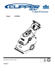
Carpet Extractor Model: 10080480 Operating Instructions (ENG) 86302100-J 10/17/08
MACHINE DATA LOG/OVERVIEW Model: Date of Purchase: Serial Number: Sales Representative: Address: Phone Number: Copyright 2006 Windsor Industries, Printed in USA OVERVIEW This carpet extractor is an electrical powered, portable carpet extractor intended for commercial use. The appliance sprays a cleaning solution onto the carpet agitates the wet carpet, and then extracts the soiled solution back into the unit’s recovery tank. The appliance is fitted with and a hand tool for cleaning upholstery and stairs.
TABLE OF CONTENTS Machine Data Log/Overview................................2 Table Of Contents ................................................3 HOW TO USE THIS MANUAL How To Use This Manual.....................................1-1 SAFETY Important Safety Instructions ............................ 2-1 Hazard Intensity Level....................................... 2-2 Grounding Instructions ...................................... 2-3 Safety Label Location........................................
HOW TO USE THIS MANUAL This manual contains the following sections: - HOW TO USE THIS MANUAL SAFETY OPERATIONS MAINTENANCE PARTS LIST The HOW TO USE THIS MANUAL section will tell you how to find important information for ordering correct repair parts. Parts may be ordered from authorized dealers. When placing an order for parts, the machine model and machine serial number are important. Refer to the MACHINE DATA box which is filled out during the installation of your machine.
SAFETY IMPORTANT SAFETY INSTRUCTIONS When using an electrical appliance, basic precaution must always be followed, including the following: READ ALL INSTRUCTIONS BEFORE USING THIS MACHINE. This machine is for commercial use. To reduce the risk of fire, electric shock, or injury: Connect to a properly grounded outlet. See Grounding Instructions. Do not leave the machine unattended. Unplug machine from outlet when not in use and before maintenance or service. Use only indoors.
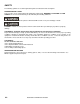
SAFETY The following symbols are used throughout this guide as indicated in their descriptions: HAZARD INTENSITY LEVEL There are three levels of hazard intensity identified by signal words -WARNING and CAUTION and FOR SAFETY. The level of hazard intensity is determined by the following definitions: WARNING - Hazards or unsafe practices which COULD result in severe personal injury or death. CAUTION - Hazards or unsafe practices which could result in minor personal injury or product or property damage.
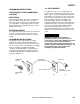
SAFETY GROUNDING INSTRUCTIONS 120 VOLT MODELS: THIS PRODUCT IS FOR COMMERCIAL USE ONLY. This appliance is for use on a nominal 120-volt circuit, and has a grounded plug that looks like the plug in “Fig. A”. A temporary adaptor that looks like the adaptor in “Fig. C” may be used to connect this plug to a 2-pole receptacle as shown in “Fig. B”, if a properly grounded outlet is not available. The temporary adaptor should be used only until a properly grounded outlet (Fig.
SAFETY SAFETY LABEL LOCATION NOTE: These drawings indicate the location of safety labels on the machine. If at any time the labels become illegible, promptly replace them.
OPERATIONS TECHNICAL SPECIFICATIONS ITEM DIMENSION/CAPACITY Construction Vacuum Motor Steel chassis with rotationally molded polyethylene tanks Three stage, bypass, 1.5 hp (1,119 watts), 100 cfm (2.8m³/min), 120” (3050 mm) waterlift 100 psi (7 bar) – Restorative 50 psi (3.5 bar) - Interim 1/2 hp (604 watts) AC with circuit breaker protection 2 x 16” (406 mm), ABS core, Perform Alert™ bristle spiral pattern 16” (40.
OPERATIONS TECHNICAL SPECIFICATIONS ITEM Height Length Width Width of scrub path MEASURE 43 inches (1092 mm) 40.5 inches (1029 mm) 22 inches (559 mm) 16 inches (406 mm) HEIGHT LENGTH WIDTH SPECIAL NOTES: This appliance is not intended for use by persons (including children) with reduced physical, sensory or mental capabilities, or lack of experience and knowledge, unless they have been given supervision or instruction concerning use of the appliance by a person responsible for their safety.
OPERATIONS HOW THIS MACHINE WORKS This carpet extractor is an electrical powered, portable carpet extractor intended for commercial use. The appliance sprays a cleaning solution onto the carpet agitates the wet carpet, and then extracts the soiled solution back into the unit’s recovery tank. The appliance is fitted with and a hand tool for cleaning upholstery and stairs. The machine is designed to maintain your carpet using the Encapsulating Interim Carpet Cleaning Process.
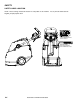
OPERATIONS-COMPONENTS 1 2 3 4 8 6 7 5 1. 2. 3. 4. 5. 3-4 Control Panel Recovery Dome Recovery Drain Hose Recovery Tank Scrub Deck 6. 7. 8. 9.
OPERATIONS-COMPONENTS 3 5 1 2 4 6 7 1. Hand Tool Switch 2. Main Switch 3. Light Cleaning 4. 5. 6. 7.
OPERATIONS-FILLING THE SOLUTION TANK Do not put defoamer, solvents, spotter or prespray chemicals in the solution tank. Do not allow water to spill into vacuum motor inlet. Dry spills from top of solution tank. Use only the suitable chemicals listed below. Using incompatible chemicals will damage the machine. Damages of this type are not covered under warranty. Carefully read ingredients on manufacturer’s label before using any product in this machine.
OPERATIONS-PRE RUN SETUP Remove electrical cord and literature from recovery tank. Fill solution tank (see filling instructions). STEP 1 Plug cord into grounded outlet. NOTE: Be sure dome is seated on recovery tank, and float shutoff is installed correctly. STEP 2 Switch the cleaning mode switch to the desired process. A for the encapsulating Interim Carpet Cleaning Process. B for Deep Extraction. STEP 3 Adjust handle to comfortable operating position.
OPERATIONS-PRE RUN SETUP Lower machine to floor. STEP 5 Select continuous setting to start solution spray or select intermittent setting to enable use of trigger switches to start solution spray. The intermittent setting requires the operator to hold any one of the three trigger switches in the “on” position with the fingers, and is typically used in small areas where short cleaning passes are made.
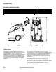
OPERATIONS-OPERATING THE MACHINE 2 1 1. This machine can be operated in either direction. For smaller areas operate the machine by pulling rearward. 2. For larger unobstructed areas, flip the handle and use the machine’s brush assisted propelling motion. STEP 1 Start at wall closest to power outlet. For small areas, pull straight back without pushing down on handle. STEP 2 1 ft.
OPERATIONS-OPERATING THE MACHINE Start at wall closest to power outlet. For large areas flip handle and operate machine in parallel passes, overlapping brush path. Clean perimeter last. ALTERNATE CLEANING PATH VACUUM INTAKE SOLUTION INTAKE STEP 5 During operation, observe the following: This machine is equipped with clear dome to facilitate operator viewing of dirty solution and vacuum air flow. During operation, observe the vacuum intake.
OPERATIONS-OPERATING THE MACHINE To speed drying, use a Windblower™ fan. Empty recovery tank by releasing recovery drain hose. Use a hose with cold water to clean out the recovery tank. Also drain solution tank after each use.
OPERATIONS-USING THE HAND TOOL Use only acceptable accessory tools. See Optional Accessories section. To connect solution hose pull back collar and insert over machine mounted fitting, then release collar to lock into place. Solution connection can remain connected at all times. HAND TOOL CONNECTION Disconnect vacuum hose and connect the hand tool to hand tool connection as shown. SOLUTION QUICK DISCONNECT STEP 1 HAND TOOL POSITION Select hand tool switch.
MAINTENANCE-SERVICE SCHEDULE SERVICE SCHEDULE MAINTENANCE Check machine for cord damage Check recovery dome and gasket for damage and cleanliness Check brushes – should be clean with no lint or strings attached Inspect vac shoe for blockage; remove fibers with coat hanger, etc.
MAINTENANCE-COMPONENTS 6 2 4 1 LEFT 3A BOTTOM 5 3B 1. Vacuum Motor 2. Solution Strainer 3A. Spray Jet-Extraction 3B. Spray Jet-Interim 4-2 4. Interim Solution Pump 5. Main Solution Pump 6.
MAINTENANCE-PERIODIC PERIODIC MAINTENANCE 3. After each use, rinse tank with fresh water. Twice a month, flush a white vinegar solution (One quart vinegar to two gallons of water) or antibrowning solution (mixed as directed) through the extractor. This will prevent build-up of alkaline residue in the system. If spray jets become clogged, remove the spray tips, wash them thoroughly, and blow-dry. NOTE: Do not use pins, wire, etc. to clean nozzles as this could destroy spray pattern.
MAINTENANCE-CIRCUIT PROTECTION CIRCUIT BREAKERS CIRCUIT BREAKERS Circuit breakers interrupt the flow of power in the event of an electrical overload. When a circuit breaker is tripped, reset it by pressing the exposed button. If a circuit breaker continues to trip. The cause should be found and corrected. 15 Amp. Protects the vacuum motor. 8 Amp. Protects the brush motor.
MAINTENANCE-SCRUB DECK 1 3 4 2 1. 2. 3. 4.
MAINTENANCE-SCRUB DECK SCRUB HEAD SCRUB BRUSH REPLACEMENT The dual cylindrical scrub head is designed to scrub chemical into the carpet. The two counter rotating brushes raise the pile of the carpet, giving it a lush groomed appearance. The rear brush is the stiffer brush and is intended to scrub deeper and help propel the machine. It can be identified by its black color. The front brush is the softer brush and is intended to lift and groom the carpet pile. It can be identified by the white bristles.
MAINTENANCE-VACUUM MOTOR ONLY QUALIFIED MAINTENANCE PERSONNEL ARE TO PERFORM THE FOLLOWING REPAIRSVACUUM MOTOR REPLACEMENT 1. Turn off all switches and unplug machine. 2. Remove recovery tank. 3. Remove the (2) screws that fasten the solution Vacuum Motor Carbon Brushes Replacement End Cap Carbon Brushes WARNING: The green ground wire must be attached for safe operation. See wiring diagram. tank to the frame, and tilt tank back to expose the inside of the frame. 4.
MAINTENANCE-TROUBLESHOOTING PROBLEM No Power, Nothing Runs Vacuum Motor Will Not Run Vacuum Motor Runs But Suction Is Poor Poor Or No Water Flow (Carpet Is Streaky) CAUSE Is the cord plugged in. Circuit breaker tripped in building. Faulty switch. Faulty power cord or pigtail. Vacuum circuit breaker tripped. Faulty main vacuum switch. Loose wiring. Faulty vac motor. Debris lodged in vac shoe. Dome gasket defective or missing. Vacuum hose cracked or hose cuff loose.
PARTS LIST 86302100 CLIPPER DUO 10/02/07
BRUSH DECK 5-1 86302100 CLIPPER DUO 10/02/07
BRUSH DECK REF PART NO. PRV NO.
BRUSH DECK MOTOR 5-3 86302100 CLIPPER DUO 10/02/07
BRUSH DECK MOTOR REF PART NO. PRV NO. QTY DESCRIPTION 1 2 3 4 5 6 7 8 9 10 11 12 13 14 15 86273750 86173340 86010630 86215880 86222120 86222290 86217250 86217260 86172960 86225790 86005640 86002390 86198450 86276820 86216750 70011 87514 87013 140929 53274 57308 22105 22106 70910 87504 57030 20063 20005 70740 20098 6 6 6 2 1 3 2 1 2 3 3 1 3 3 1 SCR, 1/4-20 X 5/8 HHCS SS WASHER, SPLIT LOCK, 1/4 SS WASHER, 1/4 ID X 5/8 OD SS BRKT, MOTOR MOUNT MOTOR, 115V, 0.
BRUSH DECK MOUNTING 1 7 7 8 2 3 4 5 2 10 19 3 2 3 4 11 15 12 9 16 6 13 20 3 17 18 14 5-5 86302100 CLIPPER DUO 10/17/07
BRUSH DECK MOUNTING REF PART NO. PRV NO. QTY DESCRIPTION 1 2 3 4 5 6 7 8 9 10 11 12 13 14 15 16 17 18 19 20 86302710 86270830 86010670 86259410 86296450 86228990 86277130 86295010 86294940 86294950 86270990 86010650 86071800 86225790 86006580 86301870 86008460 86296480 86295020 86271840 57023 87029 87206 09153 70795 57090 87018 141001 87504 70085 80102 57285 1 11 13 4 1 4 8 1 1 1 4 4 2 1 2 1 2 2 1 1 DEFLECTOR, SPRAY NUT, 5/16-18 HEX NYLOCK SS WASHER, 5/16 FLAT SS WASHER, THRUST .51 ID X 1 OD X .
CONTROL PANEL 22 7 15 17 1 13 14 16 7 8 19 6 9 11 4 19 3 2 12 23 21 25 20 24 5 18 10 25 5-7 86302100 CLIPPER DUO 07/09/08
CONTROL PANEL REF PART NO. PRV NO.
DECAL 5 1 2 3 4 5-9 86302100 CLIPPER DUO 10/17/07
DECAL REF PART NO. PRV NO. QTY DESCRIPTION 1 2 3 4 5 86221470 86244680 86004970 86298670 86295620 501208 501205 50990 - 1 1 1 1 1 LABEL, ACCESSORY LABEL, CLIPPER DUO LABEL, WINDSOR LOGO DOMED LABEL, BRUSH INSTALL LABEL, CTRL PNL CLP DUO 86302100 CLIPPER DUO 10/17/08 SERIAL NO.
HAND TOOL 4 3 5 2 1 5-11 86302100 CLIPPER DUO 10/02/07
HAND TOOL REF PART NO. PRV NO. QTY DESCRIPTION 1 2 3 4 5 86200810 86293280 86293290 86293500 86293750 270-11 - 1 1 1 1 1 NIPPLE, 1/8 FPT QD FEM BRASS HOSE, 1/4” RETRACTABLE HOSE ASM, 38.1 X 711 BLK VAC HANDTOOL ASM RETAINER, SOLUTION HOSE 86302100 CLIPPER DUO 10/02/07 SERIAL NO.
HANDLE 3 1 5 1 1 2 10 8 7 6 4 9 5-13 86302100 CLIPPER DUO 10/17/08
HANDLE REF PART NO. PRV NO. QTY DESCRIPTION 1 2 3 4 5 6 7 8 9 10 86215340 86224500 86218660 86223830 86173000 86293400 86218960 86218950 86218640 86218630 140318 730417 38353 70927 70914 41575 41574 38351 38350 3 4 1 1 3 4 1 2 1 1 BEZEL, SWITCH SPACER, HANDLE EXTRUSION HANDLE, GRIP SCR, M8X40, SHCS, ISO 4762, SST SCR, KA40X20, PT OVAL, WN1412, PL SCR, M5X12 SHCS GR 10.
HANDLE BRACKET 15 15 13 12 3 14 4 9 10 2 1 6 11 3 10 7 8 4 5 5-15 86302100 CLIPPER DUO 10/17/07
HANDLE BRACKET REF PART NO. PRV NO. QTY DESCRIPTION 1 2 3 4 5 6 7 8 9 10 11 12 13 14 15 86276800 86279170 86296830 86296860 86296880 86296890 86296920 86296970 86296980 86302860 86298840 86233170 86005640 86274400 86298830 70734 87093 20054 57030 70194 - 5 6 2 2 1 1 1 1 1 2 1 1 1 4 2 SCR, 10-32 X 3/8 HHMS SS WASHER, #10 X 1.
HANDLE MOUNTING 2 8 6 2 4 7 5 3 1 4 5-17 86302100 CLIPPER DUO 10/02/07
HANDLE MOUNTING REF PART NO. PRV NO. QTY DESCRIPTION 1 2 3 4 5 6 7 8 86274400 86006950 86276490 86010670 86295760 86295770 86297100 86297220 70194 70532 70670 87029 - 2 6 6 6 2 2 2 1 SCR, 1/4-20 X 5/8 BHCS SCR, 10-32 X 1/2 PPHMS BLK NP SCR, 5/16-18 X 5/8 HHCS SS WASHER, 5/16 FLAT SS CAP, HANDLE, OUTER CAP, HANDLE, INNER BRUSH, HANDLE CAP PANEL, CONN. ACCESS 86302100 CLIPPER DUO 06/06/08 SERIAL NO.
HANDLE RELEASE LEVER 3 7 5 10 6 4 9 15 17 16 11 8 12 2 14 18 1 13 4 5-19 86302100 CLIPPER DUO 07/09/08
HANDLE RELEASE LEVER REF PART NO. PRV NO.
RECOVERY TANK 1 2 7 8 6 3 9 5 10 4 11 5-21 86302100 CLIPPER DUO 10/02/07
RECOVERY TANK REF PART NO. PRV NO. QTY DESCRIPTION 1 2 3 86217680 86218180 86003630 28068 35370 34351 1 1 1 4 86299180 - 1 5 6 7 8 9 10 11 86297250 86006950 86004500 86004510 86002400 86296640 86233140 70532 41390 41391 20064 20041 1 2 1 1 1 1 1 DOME, 2 HOSE GASKET, DOME FLOAT SHUT-OFF TANK, RECVRY, DK GRAY (TRIMMED) HOOK, WIREFORM, HANDTOOL SCR, 10-32 X 1/2 PPHMS BLK NP HOSE, CAP HOSE, INSERT CLAMP, 2.0” WORM GEAR X .312W HOSE, 1.5 X 19.0 DRAIN CLAMP, 2.
SOLUTION 2 4 11 17 3 15 19 20 7 21 13 18 14 15 12 8 1 9 16 5 3 10 14 15 5-23 86302100 CLIPPER DUO 10/17/08 6
SOLUTION REF PART NO. PRV NO.
SOLUTION 17 2 21 20 14 18 20 34 13 7 27 29 26 7 9 1 28 30 2 27 1 3 1 26 1 6 12 36 5 35 16 15 1 11 3 1 1 4 25 8 35 19 24 7 10 23 27 1 7 3 32 22 27 33 39 37 38 5-25 3 86302100 CLIPPER DUO 10/17/08
SOLUTION REF PART NO. PRV NO.
SOLUTION TANK 5-27 86302100 CLIPPER DUO 10/02/07
SOLUTION TANK REF PART NO. PRV NO.
VAC SHOE 5-29 86302100 CLIPPER DUO 10/02/07
VAC SHOE REF PART NO. PRV NO. QTY DESCRIPTION 1 2 3 4 5 6 7 8 9 86225650 86218110 86218270 86218260 86223230 86172950 86293170 86293190 86293180 85087 35363 35380 35379 85089 70909 - 1 1 2 1 1 12 1 2 1 VACUUM SHOE, 18" GASKET, 18” VAC SHOE OUTER GASKET, 18 “ VAC SHOE SIDE GASKET, 18” VAC SHOE CENTER PLATE, 18” VACUUM SHOE SCR, M5X12, SHCS, ISO4762, SS WIPER ASM 18” PIN, CLEVIS BEARING, BRONZE FLANGED 86302100 CLIPPER DUO 10/02/07 SERIAL NO.
VAC SHOE MOUNTING 5-31 86302100 CLIPPER DUO 10/02/07
VAC SHOE MOUNTING REF PART NO. PRV NO. QTY DESCRIPTION 1 2 3 4 5 6 7 8 9 10 11 12 13 14 15 16 17 18 86003010 86004290 86002390 86297470 86276490 86010670 86295030 86278280 86296510 86005810 86259420 86272750 86010730 86298080 86259410 86010630 86273750 86293160 27759 39491 20063 70670 87029 70350 57245 87232 67010 87088 87206 87013 70011 - 1 1 1 1 2 2 2 2 1 2 2 1 1 2 2 2 2 2 CUFF. HOSE 1.5” BLK A 2161 HOSE, 1.5 BLK VAC X 45” CLAMP, 1.75” WORM GEAR X .
VACUUM 1 2 3 6 4 5 5-33 86302100 CLIPPER DUO 10/17/07
VACUUM REF PART NO. PRV NO. QTY 1 2 3 86300300 86217480 86299250 270805 - 4 1 1 4 86002390 20063 1 5 6 86004290 86302620 39491 - 1 1 DESCRIPTION SERIAL NO. FROM NOTES: SCR, #8 X 2” PPHSMS COVER, VAC MOTOR ASSY, VAC MOTOR CLAMP, 1.75” WORM GEAR X .312 HOSE, 1.
WHEEL & AXLE 3 4 2 1 5 6 7 2 1 5-35 86302100 CLIPPER DUO 10/02/07
WHEEL & AXLE REF PART NO. PRV NO. QTY 1 2 3 4 5 6 7 86276490 86010670 86219480 86001660 86226050 86010730 86294920 70670 87029 41567 41236 89279 87088 - 5 5 2 2 2 2 1 DESCRIPTION SERIAL NO. FROM NOTES: SCR, 5/16-18 X 5/8 HHCS SS WASHER, 5/16 FLAT SS HUBCAP, 9.75” WHEEL HUBCAP, 5/8” SHAFT WHEEL, 9.75” X 1.5” WASHER, 5/8 ID X 1.18 X .
WIRING DIAGRAM HANDLE CONSOLE BLU BLU BLU HANDLE SWITCH #2 HANDLE SWITCH #1 HANDLE SWITCH #3 BLK BLK BLK BLU 4 ORG 6 VAC MOTOR CIRCUIT BRKR 9 3 9 8 RELAY BLU SWITCH SWITCH SWITCH 90 F/I 90 F/I DEEP CLEAN ALL ON 1 90 F/I BRN 5 PIGGYBACK BLU 9 90 F/I PIGGYBACK 90 F/I BLK CONTINUOUS 90 F/I 90 F/I WHT 90 F/I WHT RED 13 14 PIGGYBACK PIGGYBACK BRUSH MOTOR CIRCUIT BRKR 90 F/I ORG TRANSFORMER 90 F/I ACCESSORY 90 F/I LIGHT CLEAN BUTTON SPRAY PIGGYBACK WHT RED BLK 5 7 CTRL PN
WIRING DIAGRAM REF 1 2 3 4 5 6 7 8 9 10 11 12 13 14 PART NO. PRV NO. QTY 86296060 86297750 86298180 86296010 86296020 86295980 86268210 86295990 86296000 86299330 86299370 86299340 86299360 86294220 88205 - 1 1 1 2 1 1 1 2 2 1 1 1 1 1 DESCRIPTION SERIAL NO.
SUGGESTED SPARE PARTS PART NO. PRV NO.
SERIAL NUMBERS REF. NO.