ISr WINDSOR INDUSTRIES, INC.. 1351 W . Stanford Ave..
INSPECTION Carefully unpack and inspect your extractor for shipping damage. Each unit is operated and thoroughly inspected before shipping, and any damage is the responsibility of the carrier, who should be notified immediately. ELECTRICAL This extractor operates on a standard 15 amp 115 volt AC circuit.‘ Voltages below 105 volts or above 125 volts could cause serious damage to motors. Wiring diagram is mounted inside handle control panel of machine. ‘230volt 50Hz model available.
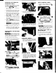
SWITCH CONTROL PANEL OPERATING THE ADM WITH ACCESSORY TOOLS 1. Remove screws holding rear panel. Repair or replace switches as req uired. The ADM is easily adapted for use with the following Windsor accessory tools; DHT-UPH3 SW - SFW SWIPRO. - - 1. Turn solution valve to “Accessory Tool” position. 2. Remove recovery hose (white cuff) from ADM dome and insert vacuum hose for accessory tool in its place. 3. Attach solution hose from accessory tool to brass solution nipple on lower back of ADM chassis.
2. Tilt machine back on handle. Remove exhaust deflector and Hex retaining nut from PVC muffler. Repair or replace as required. VAC MOTOR 1. Remove hose from exhaust horn on motor. SOLENOID & SOLUTION VALVES 2. Remove (2) screws holding vac exhaust deflector. set aside. 3. Tilt machine back on handle. Remove (2) bolts holding vac motor mounting bracket to base. Return machine to upright position. Disconnect wire leads ar?d remove vac motor. 4. To inspect motor brushes, remove brush holder assembly.
2. Inspect and clean filter screen in 3. 4. 5. 8. solution tank. Flush pumping system with 1 to 3 gallons of clean, hot water. Rinse recovery tank with clean water. Check for and remove any lint or debris around brush and vac.shoe. Check spray jets and clean solenoid valve i f required. NOTE: Always store ADM with bruall In “store” position. b Apply silicone lubricant to solution nipple. b Periodically inspect all hoses, electrical cables, filters and connections on your machine.
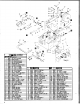
56 VAC & PUMP ASSEMBLY I(EY PARTNO. DESCRIPTION ONLY KEY PARTNO. ~ R I P f l O N 1 MY PMTNO.
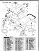
- ...-. BRUSH HOUSING & MOTOR ASSEMBLY 7 BRUSH HOUSING & MOTOR P R H S LIST UI runm. ~~~lllni~ll - 7 .
HANDLE/CONTROL llcl rmm. aascntmo* PANEL ASM.
TANKS PARTS LIST TANK ASSEMBLY n 9
115 VOLT WIRING DIAGRAMS Handle Control Panel Section Chassis Section VACUUM SWITCH 0 K ,I INTERMITTENT SPRAV SWITCH BRvyl SWITCH CIRCUIT BREAUER OUzIll 230 VOLT WIRING DIAGRAMS Chassis Section P BRUSH MOTOR 10
2 2 3 3 q 5 3 .-. WINDSOR LIMITED WARRANTY WINDSOR warrants to the original purchaserluser that this product is free from defects in workmanship and materials under normal use and service for a period of one year from date of purchase. WINDSOR will at its option, repair or replace without charge, except for transportation costs, parts that fail under normal use and service when operated and ,maintained in accordance with the applicable operation and instruction manuals.