
Service manual


OPERATING THE ADM WITH
ACCESSORY
TOOLS
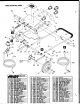
The ADM is easily adapted for use with
the following
Windsor accessory tools;
1.
Turn solution valve to “Accessory
Tool” position.
2.
Remove recovery hose (white cuff)
from ADM dome and insert vacuum
hose for accessory tool in its place.
3.
Attach solution hose from accessory
tool to brass solution nipple on lower
back of ADM chassis. (See
“8” in
Diagram
1
)
4.
Make sure that solution tank has
cleaning solution and that recovery
tank and dome are in place and ready
for operation.
5.
Switch on ADM’s vacuum and con
-
tlnous solution switches only. Use
accessory tools as with any standard
extractor.
WARNING:
Do not switch on brush
switch when operating the ADM with
accessory tools. Carpet damage may
occur.
6.
Make sure that the solution valve is
returned to the “Carpet Spray” po
-
sition before using the ADM ,again
for self
-
contained carpet cleaning.
DHT
-
UPH3
-
SW
-
SFW
-
SWIPRO.
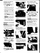
MAINTENANCE INSTRUCTIONS
FOR
ADM
WARNING:
Remove machine power
cord from electrical source before mak
-
ing any adjustments or repairs to the
machine. Only qualified maintenance
personnel are
to
perform repairs.
To
adjust handle locking cam
lever
1.
Loosen cam lever and hand tighten
knob on cam lever rod as required.
2.
Tilt machine back on handle and re
-
move brush pulley guard.
CONTINUOUS
I
BRUSH SWITCH
PUMP
SWITCH
VAC
SWITCH
I
3.
Remove shaft retaining screws and
washers from each end of brush
shaft. Replace brush or bearings as
required.
TRANSPORT WHEELS
1.
Remove screw and hub cap and slide
wheel off axle. Before reinstalling
wheel, clean axle and apply light coat
-
ing of silicone lubricant.
VAC SHOE
9
1.
Remove allen screws holding parallel
arms. Repair or replace
vac shoe,
parallel arms or spacers as needed.
NOTE
When reinstalling vac shoe,
make sure the wave washers are float
-
ing and not pinched between parallel
arm spacers and
vac shoe casting.
SWITCH CONTROL PANEL
1.
Remove screws holding rear panel.
Repair or replace switches as
re-
q
ui red.
BRUSH ASSEMBLYIBEARING
1.
Remove belt guard and ‘‘roll” belt off
motor pulley.
SUPPORT ROLLER
1.
Tilt machine back on handte. Loosen
lock nuts on each end of roller axle
and remove roller assembly. Repair
as required. Before reinstalling, clean
axle and apply a light coating of sili
-
cone lubricant.
I I
i
I
,
CIRCUIT BREAKER INTERMITTENT
PUMP
SWITCH
SWITCH
PANEL
CAUTION:
When replacing switches,
make sure wire leads are connected
to proper terminals. Refer
to
wiring
diagram located on back panel
(or
service manual) for assistance.
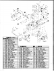
TO ACCESS VAC, PUMP
and
BRUSH
MOTOR
1.
Remove solution from both tanks.
2.
Remove dome and recovery tank.
3.
Tilt machine back on handle and re
-
move nuts holding solution tank to
base.
4.
Return machine to upright position.
Raise tank and remove solution inlet
hose from pump.
5.
Remove
(2)
vacuum hoses from tube
bracket and lay tank aside.
3