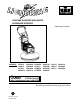
PROPANE POWERED HIGH SPEED BURNISHER/STRIPPER Operating Instructions MODELS: L21H13 L24H13 L27H13 LS30H13 10023000 10023040 10023080 10023110 LS30H13 L21K17 L24ER22 L27ER22 10023110 L21K13 10023010 10023020 L24K17 10023060 10023030 L27K17 10023090 10023070 Read these instructions before using the machine C 86039180 05/23/07 PRV NO.
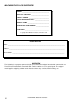
MACHINE DATA LOG/OVERVIEW MODEL _______________________________________ DATE OF PURCHASE __________________________ SERIAL NUMBER ______________________________ SALES REPRESENTATIVE # _____________________ DEALER NAME ________________________________ OPERATIONS GUIDE NUMBER ___________________ PUBLISHED __________________________________________ Copyright 2002 Windsor Industries, Printed in USA YOUR DEALER Name: _____________________________________________________________________________________________
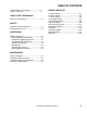
TABLE OF CONTENTS Machine Data Log/Overview.........................2 Table of Contents..........................................3 HOW TO USE THIS MANUAL How to use this Manual.................................1-1 SAFETY Important Safety Instructions ........................2-1 Hazard Intensity Level. .................................2-2 OPERATIONS GROUP PARTS LIST 21” Deck Group. ...........................................5-1 24” Deck Group. ...........................................5-3 27” Deck Group.
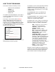
HOW TO USE THIS MANUAL This manual contains the following sections: - - HOW TO USE THIS MANUAL SAFETY OPERATIONS MAINTENANCE PARTS LIST The HOW TO USE THIS MANUAL section will tell you how to find important information for ordering correct repair parts. Parts may be ordered from authorized Windsor dealers. When placing an order for parts, the machine model and machine serial number are important. Refer to the MACHINE DATA box which is filled out during the installation of your machine.
IMPORTANT SAFETY INSTRUCTIONS When using a propane powered appliance, basic precaution must always be followed, including the following: READ ALL INSTRUCTIONS BEFORE USING THIS MACHINE. ! WARNING: To reduce the risk of fire, explosion, or injury: Use only indoors. Do not use outdoors or expose to rain. Use only as described in this manual. Use only manufacturer’s recommended components and attachments. Maintenance and repairs must be done by qualified personnel.
HAZARD INTENSITY LEVEL The following symbols are used throughout this guide as indicated in their descriptions: HAZARD INTENSITY LEVEL There are three levels of hazard intensity identified by signal words -WARNING and CAUTION and FOR SAFETY . The level of hazard intensity is determined by the following definitions: ! WARNING WARNING - Hazards or unsafe practices which COULD result in severe personal injury or death.
MACHINE OPERATIONS Your machine is shipped ready for your operation, with exception of fuel cylinder. For hazard and safety issues, the cylinders are sent with no fuel. Prior to operation have your cylinder filled at a reputable propane dealer. ! CAUTION The fuel cylinder supplied with this machine is a DOT 4E240 propane cylinder. Cylinders not branded with DOT 4E240 on the top collar should not be used. Never use a cylinder from a barbecue, etc. on this machine.
MACHINE OPERATIONS EMERGENCY STOPPING PROCEDURE STARTING PROCEDURES In case of an emergency, the machine can be brought to an instant stop by: Stripper: ! CAUTION This machine is only as fast as you allow it to be. It is imperative that you keep the floor wet with stripping solution while stripping and remove the sludge quickly and completely. Rinsing thoroughly before re-coating with sealer or floor finish. 1. Clear all areas of all displays. Remove any dust and stickers from floor. 2.
MACHINE OPERATIONS REFUELING/STORING CYLINDERS PROPANE FUEL SYSTEM ! WARNING Adjustments and repairs to the propane fuel system can only be made by properly trained and certified Service Technicians. ! WARNING Improper adjustments will cause increased toxic emissions of carbon monoxide and may result in carbon monoxide poisoning. CHANGING OIL The manufacturer recommends 10W30 oil. 1. Run engine for 5 minutes to warm the oil. 2. Make sure machine is on level surface, pad on the floor.
MAINTENANCE ! WARNING Before attempting any maintenance procedures on the machine, close the service valve on the fuel tank and stop the engine. ! CAUTION Repairs and adjustments to the fuel system must be made by an authorized, properly trained service technician. To keep the machine in good working condition, simply follow the daily, weekly, and monthly maintenance procedures.
MAINTENANCE INSTALLING OR REMOVING PAD DRIVER OR PADS Consult an authorized distributor to assist you in selecting the correct pad for your specific needs. Pad driver installation: 1. Tip machine on the right side (dip stick down). 2. Place pad driver on drive shaft and spin pad driver clockwise to install. Pad Removal & Installation: 1. Tilt machine back on rear caster or service position. 2. Remove center-lock from pad driver. 3. Remove pad from pad holder. 4.
MACHINE TROUBLESHOOTING PROBLEM. Will not start CAUSE SOLUTION No fuel or dirt in fuel line See engine owners manual for servicing. Blown head gasket NOTE: ONLY properly trained service technicians Engine overload Should adjust or repair fuel system. Dirty air cleaner Faulty spark plug Fuel system out of adjustment Defective ignition coil Hard to start No fuel or dirt in fuel line See engine owners manual for servicing.
MACHINE TROUBLESHOOTING PROBLEM. Excess vibration CAUSE SOLUTION Bolts loose on engine or deck Pad not centered or damaged pad Incorrect oil level Center or replace pad Engine overload See engine owners manual for servicing. Dirty filter See engine owners manual for servicing. Faulty spark plug See engine owners manual for servicing.
21” DECK GROUP 1 2 3 4 7A 7B 7C 5 27 26 (4) 6A 6B 25A 25B 8 9A 9B 10 11 24 23 21 22 12 13 20 19A 19B 28 14 15 18 17 16 5-1 LIGHTNING 86039180 05/23/07
21” DECK PARTS LIST REF PART NO. PRV NO.
24” DECK GROUP 1 2 3 4 7A 7B 7C 7D 5 27 26 (4) 6A 6B 25A 25B 8 9A 9B 9C 10 11 24 23 21 22 12 13 20 19A 19B 28 14 15 16A 16B 16C 5-3 17A 17B 17C 18 LIGHTNING 86039180 05/23/07
24” DECK PARTS LIST REF PART NO. PRV NO.
27” DECK GROUP 1 2 3 4 7A 7B 7C 7D 5 27 26 (4) 6A 6B 8 9A 9B 9C 25A 25B 10 11 24 23 21 22 12 13 20 19A 19B 28 14 15 18 16A 16B 5-5 17A 17B LIGHTNING 86039180 05/23/07
27” DECK PARTS LIST REF PART NO. PRV NO. QTY 1 2 86262580 86262870 07093 07083 1 1 FOAM HAND GRIPS FM HANDLE N/A ref ENGINE OWNER’S MANUAL KEY SWITCH PLASTIC HOLDER BATTERY BOX 6” KEY SWITCH BRACKET KAWASAKI 17HP HONDA 390 13HP ONAN P248 ONAN E124 PULLEY 3.5 BATTERY CONNECTOR E124 BATTERY CONNECTOR KAWASAKI BATTERY CONNECTOR ONAN P248 BATTERY 12VOLT HOUR METER DECK 27” BLUE BUMPER MOULDING LABEL, LIGHTNING PRPN WINDSOR FRONT BEARING ASSY.
30” STRIPPER GROUP 1 6A 6B 6C 2 36 3 37 4 34 7 8 35 5A 5B 9 38 13A 13B 14 16 33 32 10 14 15 11 17 31 30 29 29 12 19 18A 18B 20 27A 27B 21 22 26 23 28 24 25 5-7 LIGHTNING 86039180 05/23/07
30” STRIPPER PARTS LIST REF PART NO. PRV NO.
KAWASAKI FUEL LOAD BLOCK REF PART NO. PRV NO. QTY 1 2 3 4 5 6 7 8 9 10 86262270 86262620 86263340 86262790 86263510 86262650 86263420 86262030 86261870 86262660 07134 07103 07156 07135 07007 07132 07155 07100 07101 07133 1 1 1 1 1 1 1 1 1 1 SERIAL NO.
KAWASAKI WIRING DIAGRAM - STARTER + M 12 V BATTERY CHARGING SYSTEM KEY SWITCH ALT STATOR A-1 A-3 A-3 A-2 ENGINE HARNESS CONNECTOR A-1 BY-PASS DIODE FUEL LOCKOFF A-2 LOW OIL PRESSURE CUTOFF SWITCH (NO) HOUR METER SWITCH BLUE YELLOW BLUE YELLOW BLUE BLUE NOTE: RED WIRE CONNECTS TO LEFT SIDE OF SWITCH.
KAWASAKI FUEL SYSTEM REF PART NO. PRV NO. QTY 1 2 3 4 5 6 7 8 9 86263270 86262900 86262530 86262760 86262610 86262540 86263320 86262630 86262550 07012 07006 07009 07003 07004 07010 07118 07113 07011 1 1 1 1 1 1 1 1 1 SERIAL NO.
HONDA FUEL SYSTEM REF PART NO. PRV NO. QTY 1 2 3 4 5 6 7 8 9 10 11 12 86263270 86262900 86262530 86262760 86262610 86262540 86263310 86262880 86262330 86262520 86263500 86262890 07012 07006 07009 07003 07004 07010 07064 07065 07011 07008 07042 07005 1 1 1 3 1 1 1 1 2 1 1 1 SERIAL NO.
KILL SWITCH ASSEMBLY REF PART NO. PRV NO. QTY 1 2 86261930 86263450 07056 07050 1 1 DESCRIPTION SERIAL NO. FROM NOTES: ARM & SPRINGS (2 EACH) SWICTH MICRO (KILL) NOTE: For engine information not listed in this Standard Parts List, refer to the appropriate Engine Parts Manual.
CLUTCH AND SWITCH ASSEMBLY REF PART NO. PRV NO. QTY 1 2 3 4 5 6 86261930 86263440 86262360 86263350 86262460 86262350 07056 07049 07047 07044 07045 07043 1 1 1 1 1 1 DESCRIPTION SERIAL NO. FROM NOTES: ARM & SPRINGS (2 EACH) SWITCH (CLUTCH) CLUTCH SWITCH ASM. COMPLETE SPACER ELECTRIC CLUTCH CLUTCH ARM NOTE: For engine information not listed in this Standard Parts List, refer to the appropriate Engine Parts Manual.
BELT CHART/NOTES PART NO. PRV NO.