Operating Instructions (ENG) FLOOR POLISHER MODELS: SP13 SP15 SP17 SP20 SP17X SP20X SPDS20 Read these instructions before using the machine.
MACHINE DATA LOG/OVERVIEW MODEL______________________________ DATE OF PURCHASE ________________ SERIAL NUMBER____________________ YOUR DEALER Name: __________________________________________________________________________________________________ Address: _______________________________________________________________________________________________ For the name and address of your dealer contact: Windsor Industries Phone Number: __________________________________________________________________________
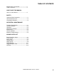
TABLE OF CONTENTS Machine Data Log/Overview. .........................2 Table of Contents ...........................................3 HOW TO USE THIS MANUAL How to use this Manual..................................4 SAFETY Important Safety Instructions.........................1-1 Hazard Intensity Level. ..................................1-2 Grounding Instructions...................................1-3 OPERATION / MAINTENANCE Technical Specifications ................................2-1 Handle Installation.
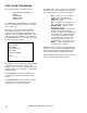
HOW TO USE THIS MANUAL This manual contains the following sections: - - HOW TO USE THIS MANUAL SAFETY OPERATIONS MAINTENANCE PARTS LIST The HOW TO USE THIS MANUAL section will tell you how to find important information for ordering correct repair parts. Parts may be ordered from authorized Windsor dealers. When placing an order for parts, the machine model and machine serial number are important. Refer to the MACHINE DATA box which is filled out during the installation of your machine.
IMPORTANT SAFETY INSTRUCTIONS When using an electrical appliance, basic precaution must always be followed, including the following: READ ALL INSTRUCTIONS BEFORE USING THIS MACHINE. ! WARNING: To reduce the risk of fire, electric shock, or injury: Use only indoors. Do not use outdoors or expose to rain. Use only as described in this manual. Use only manufacturer’s recommended components and attachments.
HAZARD INTENSITY LEVEL The following symbols are used throughout this guide as indicated in their descriptions: HAZARD INTENSITY LEVEL There are three levels of hazard intensity identified by signal words -WARNING and CAUTION and FOR SAFETY. The level of hazard intensity is determined by the following definitions: ! WARNING WARNING - Hazards or unsafe practices which COULD result in severe personal injury or death.
GROUNDING INSTRUCTIONS THIS PRODUCT IS FOR COMMERCIAL USE ONLY. ELECTRICAL: In the USA this machine operates on a one 15 amp nominal 120V, 60 hz, A.C. power circuit. The amp, hertz, and voltage are listed on the data label found on each machine. Using voltages above or below those indicated on the data label will cause serious damage to the motors. GROUNDING INSTRUCTIONS: This appliance must be grounded.
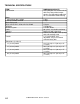
TECHNICAL SPECIFICATIONS ITEM Construction DIMENSION/CAPACITY Heavy-duty die cast aluminum deck with heavy-duty rubber bumper, tubular steel adjustable handle with die cast aluminum handle housing Motor SP13, SP15, SP17, SP20 SP17X, SP20X, SPDS20 Brush/Pad speed SP13, SP15, SP17, SP20, SP17X, SP20X SPDS20 Electrical system Cable Switches Wheels Handle Dimensions (L x W x H) 13” (33 cm) model 15” (38 cm) model 17” (43 cm) model 20” (51 cm) model 2-1 1.0 hp 1.
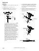
HANDLE INSTALLATION WHEN INSTALLING THE HANDLE ASSEMBLY, CHECK ORIENTATION OF THE CORD ASM AND CORD HOOK. HANDLE RECEPTACLE 4 5 6 MOTOR PLUG DECK ASSEMBLY PIVOT HOLE 3 2 1 SEE NOTE This must be installed by qualified personnel. Read all instructions thoroughly. The machine is shipped with handle unassembled. The machine is shipped with handle unassembled. Follow these steps for installation: 1. Remove handle and deck assembly from carton. 2.
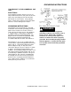
OPERATION CONTROLS 1. Safety Lock – Prevents unintended operation of the machine. 2. Switch Levers – Turns machine on/off. 3. Adjustment Handle – Allows the handle to be adjusted to a comfortable operating position. 1 2 1. To adjust handle lock, tighten nut on handle while in the locked position. Optimum locking force and ease of locking is accomplished when the locking lever nut is set to a torque of 30 to 50 inch pounds in the locked position. 2.
OPERATION DAILY MAINTENANCE ! CAUTION 1. Inspect power cord for wear. To prevent electrical shock replace cords with frayed or cracked insulation immediately. 2. Place machine in the storage position. 3. Check pad condition. Change if soiled or torn. For indoor use only. To prevent possible damage to the floor when using the brush option, use water or other approved cleaning solution while operating. When using the pad option, always keep the machine moving when in contact with the floor.
MAINTENANCE SCRUB BRUSHES Please refer to the following to assist in selecting the proper brush or pad for the work at hand. NOTE: All original equipment brushes are equipped with “Perform Alert�”. This feature will tell the operator when it is time to replace the scrub brushes. “Perform Alert�” brushes have pre trimmed bright yellow tufts to indicate the length of a worn out brush. When the tufts in the scrub brush wear to a length equal to the yellow tufts, the scrub brushes should be replaced.
TROUBLESHOOTING PROBLEM Machine will not run Electrical shock Repeated circuit breaker tripping Excessive vibration Pad does not turn but motor is running CAUSE SOLUTION Circuit breaker tripped in building. Check and reset. Power switch failure. Test switch for continuity and replace if necessary. Tripped circuit breaker. Reset. Faulty power cord. Replace. Fuse in motor is blown. Replace. CAUTION: To reduce the risk of electrical shock, unplug the machine before opening fuse holder.
BRUSH/PAD DRIVER GROUP 3 3 1A 1B 1C 1D 3-1 STORM POLISHER 980100 04/24/06 2A-W
BRUSH/PAD DRIVER GROUP REF PART NO. QTY 1A 1B 1C 1D 2A 2B 2C 2D 2E 2F 2G 2H 2J 2K 2L 2M 2N 2P 2Q 2R 2T 2U 2V 2W 3 02216 02396 02218 02219 02232 02233 02234 02235 02236 02447 02448 02445 02444 02446 02242 02240 02241 02205 02206 02239 02237 02238 02202 02203 02220 - DESCRIPTION SERIAL NO. FROM NOTES: PAD DRIVER, 13" POLISHER PAD DRIVER, 15" POLISHER PAD DRIVER, 17" POLISHER PAD DRIVER, 20" POLISHER BRUSH, 13" NYL.POL. W/CLT.PLT BRUSH, 13" NYL.SCRUB W/CLT.PLT BRUSH, 13" MILD GRIT W/CLT.
FRAME GROUP 20 1 21 22 23 2 19 3 18A 18B 18C 18D 4 5 6 7 8 9 MOTOR ASM SEE PG 3-5 17A 17B 17C 17D 3-3 8 14 15 16 11 12 13 STORM POLISHER 980100 03/08/03 10
FRAME GROUP REF PART NO. QTY 1 2 3 4 5 6 7 8 9 10 11 12 13 14 15 16 17A 17B 17C 17D 18A 18B 18C 18D 19 20 21 22 23 78447 38290 57275 51328 87203 57276 89206 87054 70262 70135 730008 87067 70698 70691 87211 27871 14341 14371 14372 14373 29211 29212 29213 29214 03111 70701 87086 23206 730012 1 1 1 2 2 2 2 2 2 2 2 4 4 2 2 2 1 1 2 1 1 DESCRIPTION SERIAL NO. FROM NOTES: TUBE ASSY, HANDLE ADJ HANDLE, POLISHER NUT, M10X1.5 HEX NYLOCK PLTD LINK, HANDLE ADJUST WASHER, 14MMID X 36MMOD NUT, PUSH FLAT RD .
MOTOR GROUP 6 2 4 4 1 1 5 3 12 12 11 11 SP13, SP15, SP17, SP20 SP17X, SP20X 10 7 8 9 12 11 SPDS20 3-5 STORM POLISHER 980100 03/08/03
MOTOR GROUP DESCRIPTION SERIAL NO. FROM NOTES: REF PART NO. QTY 1 2 3 4 27884 500763 53263 70702 1 1 1 3 COVER, MOTOR LABEL, STORM MAIN MOTOR, 1 HP 115V INDUCTION SCR, M5 X .8 X 15MM BLK 5 53264 1 MOTOR, 1.5 HP 115V INDUCTION INCLUDES ITEM 4, 1, 12, & 11 (SP17X/20X) 6 7 8 9 10 11 12 500764 27892 70700 53253 500765 70723 62917 1 1 8 1 1 6 1 LABEL, STORM DELUXE MAIN COVER, ASM, MOTOR SCR, M5 X .8 X 10MM PHMS BLK MOTOR, 115V 1.75 HP 175/300 RPM LABEL, STORM DUAL SPEED MAIN SCR, M5 X .
HANDLE GROUP 14 13 5 6 17 2 16 22 18 1 9 11 20 3 12 7 19 9 15 21 8 4 10 3-7 STORM POLISHER 980100 03/09/05
HANDLE GROUP REF PART NO. QTY 1 2 3 4 5 6 7 8 9 10 11 12 13 14 15 16 17 18 19 20 21 22 14344 140393 36196 41363 41366 51326 51327 57274 57275 500194 66334 67430 70686 70687 70689 70692 73990 78437 87086 87202 78447 14434 1 1 2 1 1 1 2 4 1 1 1 1 2 2 1 1 2 1 2 1 1 2 DESCRIPTION SERIAL NO. FROM NOTES: BAR, HANDLE ADJUST BLOCK, HANDLE MOUNT GRIP, POLISHER HANDLE HOUSING, POLISHER HANDLE REAR HOUSING, POLISHER HANDLE FRONT LOCK, SAFETY HANDLE LEVER, SWITCH NUT, M6 HEX FINISH NUT, M10X1.
WIRING GROUP PRIOR TO SN * 5 10 9 7 4 12 8 11 6 1 3 6 11 2 3-9 STORM POLISHER 980100 11/15/03
WIRING GROUP REF PART NO. QTY 1 2 3 4 5 6 7 8 9 10 11 12 20054 23167 23206 57069 70801 70689 72123 73989 73993 87057 87208 140674 1 1 1 1 2 2 2 1 1 2 2 1 DESCRIPTION SERIAL NO. FROM CLAMP, 3/8 NYLON UL/CSA CORD SET, 14/3 STO X 50' YLW CORDSET, 14/3 X 47", SJT, BLK NUT, ORG WIRE (2-5 18G/2-14G) SCR, M3.5 X 40 PHTF TYPE B SCR, M4.8 X 10 HHTF TYPE B SWITCH, 25A SPST 125-250V SNAP SPACER, SWITCH POLISHER SPRING, COMP, .48OD X .
WIRING DIAGRAM / SPARE PARTS SUGGESTED SPARE PARTS PART NO. DESCRIPTION 87202 73990 73993 72123 14344 66334 67430 34378 34379 27352 67488 140401 140411 WASHER, BEARING (HANDLE ADJ) SPRING, EXT .5 OD X 3.5L SPRING, COMP .48 OD X .91 L SWITCH. 25A SPST 125-250V SNAP BAR, HANDLE ADJ PIN, PIVOT, HANDLE ADJ ROD, HANDLE ADJ FUSE FUSE HOLDER COUPLING, MTR/GEAR BOX PLSHER RECTIFIER, 50A 600V BRIDGE CIRCUIT BREAKER, 30AMP MPX CIRCUIT BREAKER, 20AMP MP/MB 3-11 SERIAL NO.