
Industries Carpet Cleaner User's Manual


OPERATION
STORM POLISHER 980100 03/08/03
2-3
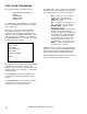
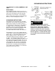
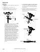
CONTROLS
1. Safety Lock – Prevents unintended operation of the
machine.
2. Switch Levers – Turns machine on/off.
3. Adjustment Handle – Allows the handle to be
adjusted to a comfortable operating position.
The handle adjust bar (14344) for the polishers
are individually preset at the factory for optimum
locking efficiency and minimum effort of
engaging. It should not be necessary to adjust
the handle adjust bar unless the relationship of
the handle adjust bar nut (57275) or fixed clamp
bolt (70692) and their corresponding nuts
(57275) and washer (87086) have been
disturbed. The handle can be positioned to be
locked with the handle adjust bar pointing either
up or down. In order to change the position the
handle and bolt must be removed and rotated
180 degrees. It is incorrect to make it lock
opposite from the way it was assembled by
applying more force to the nut. From the factory
the locking is in the up position when the
machine handle is locked. The pivot pin (66334)
on the handle adjust bar is off center, in
relationship of the screw to the axis of the (see
drawing). To adjust handle adjust bar, tighten
nut on handle while in the locked position. The
handle is locked when the screw is to the
outside of the machine and the flat on the
opposite side of the handle is flush to the
bracket.
1. To adjust handle lock, tighten nut on handle while in
the locked position. Optimum locking force and ease
of locking is accomplished when the locking lever
nut is set to a torque of 30 to 50 inch pounds in the
locked position.
2. Gap between clamp halves at the front should be to
the gap in rear when the handle adjust bar is
adjusted properly and in the locked position (gap
approximately 1/16").
2 2
1
3
LOCK
UNLOCK
LOCKING SIDE FLAT
66334
PIVOT PIN C
L
HANDLE C
L
SHOWN HANDLE IS
IN LOCK POSITION
14344
67430
87202
57275 (2)
70692
87086
2
1