® WINEGARD TM Movin’ View Digital Satellite Mobile Antenna Models MV-2222/MV-1111 Made in the U.S.A. U.S. Patent Nos. 6,023,247; 6,188,300 Winegard Company • 3000 Kirkwood St. • Burlington, IA 52601-2000 319/754-0600 • FAX 319/754-0787 • www.winegard.com Printed in U.S.A. © Winegard Company 2001 2451021 Rev.
Introduction/How Does Digital Satellite TV Work? Introduction Congratulations! You have purchased one of Winegard’s latest developments in the mobile satellite reception product line —the Movin’ ViewTM. This system, used with your digital satellite receiver, will deliver the best reception possible using GPS (Global Positioning System) and precision gyroscopes. How Does Digital Satellite TV Work? and processing take place.
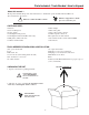
Parts Included • Tools Needed • How to Unpack About this manual — We hope this manual will provide clear instructions to install and operate the MV-2222 and MV-1111. Two symbols have been used — ! Indicates suggestions to make processes easier for you.
Installation Diagram GPS ANTENNA FIGURE 1 SWITCH LOCATION ADJUSTABLE BASE FOOT EL MOTOR HEYCO® CONNECTORS POWER SUPPLY LEVELING SCREW COUNTERWEIGHT LEVELING SCREW FRONT OF VEHICLE ! REAR ADJUSTABLE BASE FOOT s ire tie w e v t Remong moun holdi LEVELING SCREW REAR BASE FOOT MUST DIRECTLY FACE REAR OF VEHICLE AZ MOTOR ADJUSTABLE BASE FOOT REFLECTOR S:\PART-NO\1021P4 4 DVB
Installation Installing unit on roof of vehicle — ! 6. On each foot, screw the flange nut to the base of the leveling screw on the mounting foot, flange up. Place rubber washer, with the rubber side up, on the nut, Figure 2. Push mounting foot under base. Push foot screw through the base and tighten lock nut to secure foot to base. Be sure the base feet are pointing away from the base. Base feet will be removed later during install.
Installation ROOF INSTALLATION, continued GPS installation — 9. Place the unit on the roof in its permanent location and mark around the base bracket, Figure 4. (Make sure the rear adjustable base foot is directly facing the back of the coach.) The GPS antenna is pre-wired and has a 3 foot cable running through one of the Heyco® connectors.
Installation • Wiring Cable entry installation — INSTALLATION 1. Decide the best location for the cables to enter the vehicle, and the location of the switch and receiver (see “Installing the switch and receiver” below.) Drill a 1/2” hole in the roof, push wires inside. Make proper connections (remember you must have filtered +12 VDC power source). 1. Decide the location of the power on/off switch.
Installation • Wiring Connecting the receiver — Connecting two receivers MV-1111 Domed Automatic/MV-2222Tracking System Connecting first receiver: Connecting one receiver 1. Connect the coax cable from the roof to the “IN” input on the splitter (SP-2052). Connect a coax cable from one of the “OUT” ports or jack on the splitter (SP-2052). Connect other end of this cable to the “input” on the DC PASSIVE D575p demultiplexer. 2. Determine primary receiver. The primary receiver is the one used most often.
Operation Your new MV-2222/1111 features: • GPS technology • Fast signal acquisition times • Easy “one-button” operation • Ability to toggle between satellites using remote control, if subscribing to multisatellite programming • Low maintenance • Compatible with continental U.S. digital satel lite receivers • Winegard warranty • MV-2222 features precision gyroscopes To operate your system — NOTE: For Model MV-1111 vehicle must be parked. 1. Turn on receiver and television set.
Troubleshooting IF YOU DO NOT HAVE A SIGNAL: NOTE: The power rocker switch must be ON for the next steps. Voltage must be +12 VDC, except at the LNBF, see #2, Figure 9, page 11. 1. The signal may be blocked by trees, hills or structures. Pull into an area where no trees or buildings are in the line of sight from unit to the satellites. 6. To check voltage at connections, see Figure 9 on page 11. FOLLOW THE NUMERICAL SEQUENCE ON THE DRAWING AND CHECK VOLTAGE AT: #1. Power Supply. #2. LNBF voltage.
Base Diagram FIGURE 9 #4 COAX CABLE AT CONTROL BOX #3 CONTROL BOX TO LNBF #1 POWER SUPPLY (POWER WIRE, SEE DETAIL) HEYCO CONNECTORS EL MOTOR GPS ANTENNA POWER SUPPLY CONTROL BOX (DETAIL BELOW) #2 LNBF VOLTAGE AZ MOTOR A CONTROL BOX DETAIL s:\part-no\1021p11 11 8-PIN POWER AZ MOTOR TO LNBF EL MOTOR TO RECEIVER T DO NOT USE
Specifications & Warranty Features and specifications • One button operation. • Manufactured from sturdy ABS plastic, UV protected. • GPS satellite signal acquisition. • Off-white color compatible with all vehicles. • Depending on receiver type, you can access satellites 119°, 110° or 101°. • Compact size — 32” diameter, 15” height Weight of unit - 43 lbs. Shipping weight - 59 lbs. • No user input required. • No data port required for any receiver. • Tracking greater than 30°. • Elevation range 14.